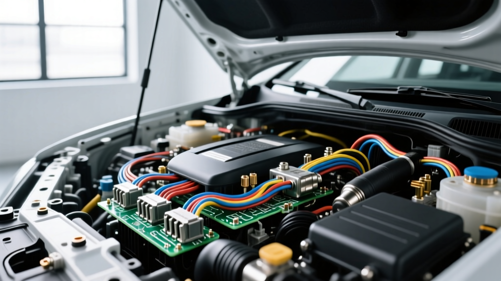
The Reality of Hi Tech Auto Electrics: Why Standard Tools Fail
Modern vehicles are no longer simple mechanical machines with basic 12-volt lighting circuits; they are rolling data centers. A late-model sedan or heavy-duty truck can contain over three miles of wiring, routing data across 70 to 100+ Electronic Control Units (ECUs). When technicians and advanced DIYers attempt to diagnose these hi tech auto electrics using only a standard Digital Multimeter (DMM) or a 12V test light, they are bringing a blunt instrument to a microsurgery.
The fundamental limitation of a standard DMM is its sampling rate. A high-quality multimeter like the Fluke 87V samples voltage roughly 4 to 5 times per second. However, a High-Speed Controller Area Network (CAN) bus operating at 500 kbit/s transmits data bits that last only 2 microseconds each. If a CAN High wire experiences a micro-short to ground that drops the voltage for 10 microseconds, a DMM will completely miss the event, displaying an averaged 'normal' voltage of 2.6V. To properly diagnose, repair, and validate hi tech auto electrics, a targeted investment in advanced diagnostic tooling is mandatory. This analysis breaks down the essential toolkit, the associated costs, and the technical specifications required to interface with modern multiplexed networks.
Essential Diagnostic Arsenal & Cost Breakdown
1. Automotive Oscilloscopes: The Network Translator
An automotive oscilloscope is the single most critical tool for analyzing hi tech auto electrics. Unlike a DMM, a modern 4-channel scope like the PicoScope 4425A samples at 20 MS/s (Mega-samples per second), capturing microsecond voltage anomalies, injector flyback spikes, and CAN bus arbitration errors in real-time. According to the Pico Technology Training Guides, visualizing the physical layer of the network allows technicians to identify resistive faults, capacitive coupling issues, and termination failures that scan tools cannot see.
- Estimated Cost: $1,400 - $1,800 (Scope, leads, and 20:1 attenuators)
- Primary Use Case: Validating CAN/LIN bus physical layer integrity, analyzing variable reluctance (VR) sensor waveforms, and measuring fuel injector peak-and-hold current ramps.
2. Thermal Imaging for Voltage Drop Detection
High-resistance connections in modern fuse boxes or power distribution modules (PDMs) generate heat before they fail completely. Using Ohm's Law and the power equation ($P = I \times V$), a mere 0.5V drop across a 15A fuse powering a fuel pump module generates 7.5 Watts of heat. A thermal imager like the FLIR E5-XT (19,200 pixels) instantly highlights this thermal signature, saving hours of back-probing and voltage drop testing with a multimeter.
- Estimated Cost: $2,200 - $2,800
- Primary Use Case: Locating corroded bulkhead connectors, failing relays, and overtaxed ground studs without dismantling the entire dash.
3. CAN Bus Analyzers & Breakout Boxes
While an oscilloscope views the physical electrical layer, a CAN analyzer translates the hex data into readable parameters. Tools like the PEAK PCAN-USB allow technicians to sniff network traffic, inject test frames, and log data at the bus level. Paired with an OBD-II breakout box, this prevents terminal damage to the vehicle's diagnostic link connector (DLC) during prolonged testing.
- Estimated Cost: $250 (Analyzer) + $80 (Breakout Box)
- Primary Use Case: Reverse-engineering proprietary CAN messages, monitoring network sleep states, and diagnosing module communication U-codes (e.g., U0100 Lost Communication with ECM).
Cost vs. Capability Matrix
| Tool Category | Industry Standard Example | Est. Investment | ROI / Cost-Saving Application |
|---|---|---|---|
| 4-Channel Scope | PicoScope 4425A | $1,499 | Prevents misdiagnosis of $800+ ECUs by proving wiring integrity. |
| Thermal Camera | FLIR E5-XT | $2,499 | Instantly locates parasitic draws and high-resistance grounds. |
| CAN Analyzer | PEAK PCAN-USB Pro | $330 | Decodes multiplexed network faults without OEM $3,000 scan tools. |
| Precision Crimper | TE Connectivity 58496-1 | $385 | Ensures OEM-spec terminal crimps, preventing warranty comebacks. |
| Current Clamp | Pico TA018 (60A/600A) | $185 | Measures starter inrush and parasitic draws down to 10mA resolution. |
Technical Specifications: Interfacing with Multiplexed Networks
Understanding the physical layer of hi tech auto electrics is mandatory before attaching diagnostic equipment. Back-probing the wrong pin or using an unshielded test lead can introduce electromagnetic interference (EMI) that crashes a network. Below are the standard specifications for the most common automotive networks.
| Network Protocol | Max Speed | Wire Gauge (AWG) | Standard DLC Pins | Termination & Topology |
|---|---|---|---|---|
| High-Speed CAN (ISO 11898-2) | 500 kbit/s | 20 - 22 AWG (0.35-0.50 mm²) | Pin 6 (CAN H), Pin 14 (CAN L) | Twisted pair, two 120Ω resistors (60Ω total across bus) |
| Single-Wire CAN (GMLAN) | 33.3 kbit/s | 18 - 20 AWG | Pin 1 (SW CAN) | Single wire, requires specific transceiver sleep/wake voltages |
| LIN Bus (ISO 9141 / 17987) | 20 kbit/s | 18 - 20 AWG | Manufacturer Specific | Single wire, 12V pull-up resistor, master/slave topology |
| FlexRay | 10 Mbit/s | Shielded Twisted Pair | Not on standard DLC | Used in high-speed chassis (BMW/Audi), requires active star couplers |
Note: As defined in the SAE J1939 standard for heavy-duty and advanced CAN networks, termination resistance is critical. If a technician measures 120 ohms across Pins 6 and 14 of the OBD-II port, it indicates one of the two terminating ECUs has dropped off the network or a harness break has occurred.
Wiring Repair: OEM Harness Replacement vs. Targeted Splicing
When a fault is isolated to a damaged harness in hi tech auto electrics, dealerships often default to replacing the entire OEM wiring harness. A modern engine-to-chassis harness for a 2020+ vehicle can exceed $1,500 in parts and require 15+ hours of labor to route through firewall grommets. A professional auto electrician, however, will perform targeted, OEM-equivalent repairs for under $50 in materials.
The Cost of Proper Terminal Crimping
Modern ECUs utilize micro-connectors like the TE Connectivity MATEnet or Molex MX150 series. These terminals feature intricate wire and insulation crimp wings. Using a generic, non-ratcheting crimp tool will deform the terminal, leading to a high-resistance joint that will fail when under-hood ambient temperatures reach 105°C. Investing in the correct manufacturer crimp die (e.g., TE 58496-1) ensures the copper strands are compressed to the exact mil-spec, creating a gas-tight connection. For harsh environments (e.g., wheel speed sensors, oxygen sensors), Deutsch DT series connectors with silicone grommets and wedgelocks remain the gold standard, costing roughly $3-$5 per mated pair.
Splicing Methodologies for Data Networks
You cannot use standard twist-on wire nuts or basic solder joints on a CAN bus. Solder creates a rigid point that can fracture under chassis vibration, and excessive solder wicking alters the wire's capacitance, reflecting CAN bus signals and causing data corruption. The approved repair method: 1. Strip the 20 AWG CAN wire using a precision micro-stripper. 2. Perform a tight Western Union (lineman's) splice. 3. Use a micro-flame or temperature-controlled iron to apply rosin-core solder sparingly. 4. Seal the repair using adhesive-lined polyolefin heat shrink (e.g., 3M FP-301). The hot-melt adhesive inside the shrink tube melts and flows around the wire strands, creating a waterproof, vibration-proof seal that matches the OEM harness flexibility.
Real-World Troubleshooting: Parasitic Draws on LIN Networks
A common issue in hi tech auto electrics is a parasitic battery draw caused by a Local Interconnect Network (LIN) bus failure. Unlike CAN, LIN is a single-wire, master-slave network often used for seat memory modules, HVAC flaps, and rain sensors. If a slave module (like a power seat switch) develops an internal fault, it may continuously pull the LIN bus voltage down from its normal 12V resting state to 8V, preventing the master module (e.g., the Body Control Module) from entering 'sleep' mode. The Fix: Instead of pulling fuses blindly, connect an oscilloscope to the LIN wire. A healthy sleep-state LIN bus will show a steady 12V line. A faulty bus will show erratic square waves or a pulled-down voltage. By isolating the specific branch circuit at the BCM connector, you can identify the exact slave module holding the network awake, turning a 6-hour guess-and-replace job into a 20-minute pinpoint test.
Conclusion: Calculating the ROI on Advanced Diagnostics
Transitioning into the realm of hi tech auto electrics requires a paradigm shift from 'parts swapping' to 'signal validation.' While the initial capital expenditure for an automotive oscilloscope, thermal imager, and precision crimping tools may approach $4,500, the return on investment is rapid. Accurately diagnosing a $5 wiring fault that an OEM dealer misdiagnosed as a $1,200 BCM failure not only pays for the tools but establishes unparalleled technical authority. By understanding AWG requirements, network termination topologies, and proper multiplexed repair strategies, technicians can conquer the most complex electrical architectures on the road today.
For further reading on automotive connector standards and repair protocols, refer to the TE Automotive Connectivity Solutions documentation.