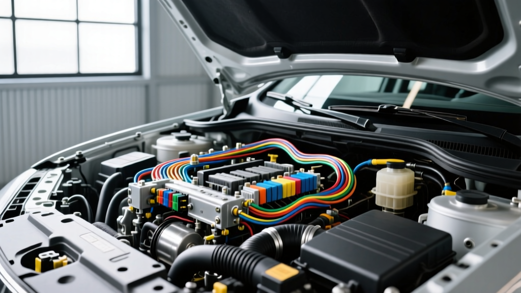
The High Cost of Amateur Automotive Wiring
When dealing with automotive electrical systems, the margin for error is razor-thin. A single poor connection, an incorrectly sized wire, or a bypassed fuse can lead to parasitic draws, catastrophic ECU failure, or devastating electrical fires. Professional repair facilities, echoing the rigorous diagnostic and safety standards historically championed by Dearborn Auto Electric technicians, consistently see the aftermath of amateur wiring jobs. Vehicles arrive with melted harnesses, corroded splices, and voltage drops that mimic failing sensors.
This guide outlines the most dangerous automotive wiring mistakes and provides actionable, SAE-compliant solutions. Whether you are installing an electric AC compressor, upgrading an alternator output, or repairing a starter circuit, adhering to these safety warnings is non-negotiable.
Mistake 1: Using Household Wire and Ignoring Insulation Ratings
One of the most frequent and dangerous mistakes is using household building wire (such as THHN or Romex) in a vehicle. Household wire is designed for static, climate-controlled environments with 120V/240V AC power. Automotive systems operate on 12V-14V DC (or up to 48V in mild hybrids), which requires significantly higher amperage to deliver the same wattage, generating immense heat in undersized conductors.
Furthermore, automotive wire must feature specialized insulation. Standard PVC insulation melts and becomes brittle under the hood. You must use cross-linked polyethylene (XLPE) insulated wires, specifically GXL, TXL, or SXL types, which are rated for continuous exposure to 125°C (257°F) and resist abrasion, oil, and battery acid.
Automotive Wire Gauge (AWG) & Ampacity Reference Chart
The following table outlines standard SAE J1128 specifications for GXL primary wire in a 14V DC system. Note that wire length heavily dictates voltage drop; runs exceeding 10 feet require stepping up one AWG size.
| AWG Size | Max Continuous Amps | Typical Automotive Application | Common OEM Color Code |
|---|---|---|---|
| 18 AWG | 6A - 8A | Sensors, ECU triggers, LED lighting | White, Yellow, Green |
| 16 AWG | 10A - 12A | Interior lighting, horn, small relays | Blue, Tan |
| 14 AWG | 15A - 18A | Fuel pumps, power windows, wipers | Purple, Light Green |
| 12 AWG | 20A - 25A | Headlights, cigarette lighter, ABS pumps | Red, Dark Green |
| 10 AWG | 30A - 40A | Electric cooling fans, power seats | Red, Black |
| 8 AWG | 50A - 60A | Alternator B+ output, rear window defrost | Red, Black |
| 4 AWG | 100A - 120A | High-output alternator main feed | Red |
| 1/0 AWG | 200A+ | Starter motor positive, main battery ground | Red, Black |
Mistake 2: The Solder-Only Fallacy in High-Vibration Zones
Many DIY enthusiasts believe that soldering a wire connection is the gold standard. In automotive applications, relying solely on solder is a critical safety hazard. Solder wicks into the wire strands via capillary action, creating a rigid, inflexible section of wire. In a high-vibration environment like a vehicle chassis or engine bay, this rigid section creates a stress riser. Over time, the wire fatigues and snaps right at the edge of the solder joint.
Additionally, solder melts at relatively low temperatures (around 188°C for standard 60/40 tin/lead). If routed near exhaust manifolds or turbochargers, a soldered joint can liquefy, causing a dead short against the chassis.
The Correct Protocol: Open-Barrel Crimping
Professional auto electricians use open-barrel crimp terminations, such as the Aptiv Metri-Pack or Weather-Pack series. A properly executed crimp creates a cold-weld, gas-tight connection where the copper strands deform into the terminal brass, leaving no room for oxygen or moisture to cause corrosion.
- Tooling: Use a precision ratcheting crimp tool (e.g., Delphi or TE Connectivity spec). The tool must not release until the crimp cycle is fully complete.
- Pull-Test: SAE standards require a specific pull-out force. A 16 AWG crimp should withstand at least 30 lbs of tensile force without the wire slipping.
- Wire Preparation: Strip the wire exactly to the terminal's bell-mouth specifications. The wire strands should be visible just past the crimp barrel, but the insulation should not be pinched inside the conductor crimp.
Mistake 3: Grounding to Painted Surfaces and Using Sheet Metal Screws
A vehicle's chassis is the return path for nearly every electrical circuit. A poor ground causes voltage drop, which leads to dim headlights, erratic sensor readings, and fuel pump starvation. The most common mistake is attaching a ground ring terminal to a painted, powder-coated, or rusted surface, or using a self-tapping sheet metal screw which provides poor thread engagement and vibrates loose.
Proper Grounding Execution
- Surface Prep: Use a wire wheel or sandpaper to remove all paint, primer, and rust down to bare, shiny metal.
- Hardware: Use a machine screw or bolt (e.g., M6 or M8) threaded into a welded nut or stamped hole. Always use a star washer (internal or external tooth) between the ring terminal and the chassis. The teeth bite through any microscopic oxidation that forms over time.
- Torque Specifications: Do not overtighten, which can strip the threads or crack the terminal. An M8 ground bolt should typically be torqued to 15–20 Nm (11–15 lb-ft).
- Corrosion Protection: After tightening, coat the entire ground connection in dielectric grease or a dedicated battery terminal protector to prevent galvanic corrosion.
Mistake 4: Bypassing Fuses and Ignoring Bus Bar Thermal Limits
When a fuse blows, it is a symptom of a fault, not the fault itself. Replacing a blown 15A mini-fuse with a 20A or 30A fuse—or worse, wrapping it in foil—is a direct path to an electrical fire. The wiring harness is engineered to handle a specific thermal load. If you over-fuse a 14 AWG wire designed for 15A, the wire's insulation will melt and ignite long before the 30A fuse blows.
Furthermore, modern fuse boxes utilize internal copper bus bars. These bus bars have strict thermal limits. If you add aftermarket accessories (like off-road light bars or winch solenoids) and draw 40A through a fuse block rated for a total of 60A, the internal plastic housing will warp and the bus bar will anneal, causing permanent resistance and heat buildup.
Symptom-Cause-Fix Decision Tree: Blown Fuses
- Symptom: Fuse blows immediately upon insertion.
- Cause: Direct short to ground before the load (e.g., pinched wire against chassis).
- Fix: Use a short-finder tool or test light to isolate the harness section. Repair with adhesive-lined heat shrink.
- Symptom: Fuse blows after 5–10 minutes of operation.
- Cause:Component thermal overload or binding motor (e.g., cooling fan motor drawing excess amps due to bad bearings).
- Fix: Measure amperage with an inline clamp meter. Replace the failing component, do not upsize the fuse.
Mistake 5: Improper Splicing and Environmental Sealing
Twist-on wire connectors (wire nuts) and standard electrical tape have absolutely no place in automotive wiring. Electrical tape unrolls when exposed to under-hood heat, exposing bare copper to moisture and causing rapid green corrosion (copper oxide), which increases resistance.
For any inline splice, you must use adhesive-lined dual-wall heat shrink. When heated, the outer polyolefin wall shrinks to provide abrasion resistance, while the inner thermoplastic adhesive melts and flows into the wire strands, creating a 100% waterproof, environmental seal. For connectors exposed to direct water spray (like wheel speed sensors or transmission solenoids), always pack the connector cavity with dielectric grease to prevent water ingress and terminal fretting corrosion.
Critical Safety Warnings for Modern Vehicles
As automotive architecture evolves, the safety risks increase. Always observe the following warnings before turning a wrench:
- Battery Isolation: Always disconnect the negative battery terminal first, and reconnect it last. This prevents accidental shorting through the chassis while working on the positive side.
- Airbag (SRS) Circuits: SRS wiring is universally identified by yellow connectors and yellow wire looms. Never probe these circuits with a standard multimeter; the small voltage output from the meter can deploy the airbag. Wait at least 15 minutes after battery disconnect for the backup capacitors to discharge.
- High-Voltage (EV/Hybrid) Cabling: Any cabling wrapped in orange loom indicates high-voltage DC (ranging from 48V to 800V). Lethal arc flash and electrocution hazards exist. Never cut, splice, or probe orange cabling without specific OEM high-voltage certification and insulated Class 0 gloves.
Conclusion
Automotive electrical work requires patience, precision, and adherence to established engineering standards. By avoiding household materials, utilizing proper crimp terminations, respecting ground path integrity, and never bypassing overcurrent protection, you ensure the longevity and safety of the vehicle. Treat every wire, pin, and fuse with the respect demanded by professional auto electric benchmarks, and your electrical modifications will survive the harsh realities of the road.