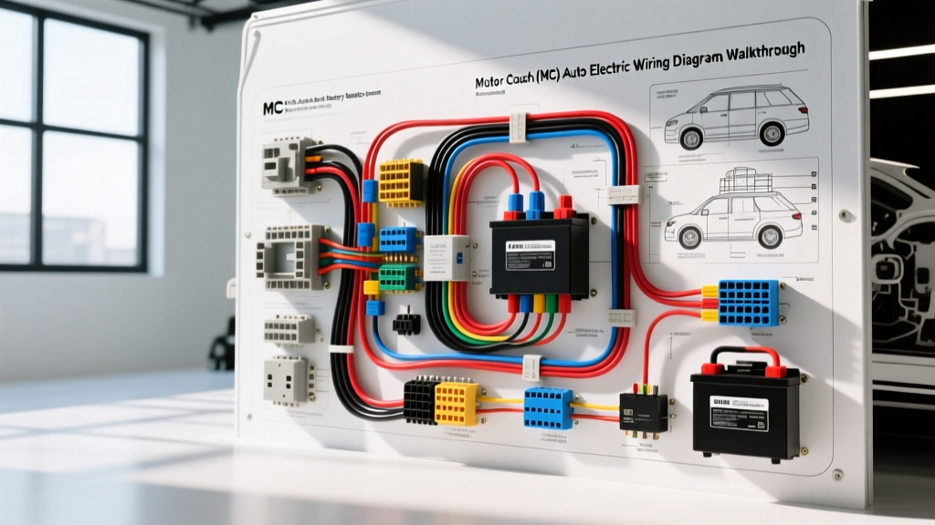
Decoding the MC Auto Electric Architecture
When technicians, upfitters, and advanced DIY builders approach a Motor Coach (MC) auto electric schematic, they are not just looking at a standard vehicle wiring harness. An MC auto electric network is a complex, dual-voltage ecosystem that bridges heavy-duty chassis power (12V/24V DC) with residential-style house systems (12V DC and 120V/240V AC). Understanding the complete wiring diagram walkthrough requires tracing current flow from the high-output alternator, through the Battery Isolation Manager (BIM), into the house battery bank, and finally through the inverter/charger multi-conductor (MC) harnesses.
This guide provides a comprehensive, pin-by-pin and cable-by-cable walkthrough of a modern Class A and Class C motor coach electrical architecture. We will reference RV Industry Association (RVIA) standards and SAE J1171 marine/RV electrical guidelines to ensure all wire gauges, torque specifications, and routing protocols meet rigorous safety benchmarks.
Phase 1: High-Output Alternator and Chassis Charging Circuit
The foundation of any MC auto electric system is the chassis charging circuit. Standard passenger vehicle alternators (typically 130A-150A) are insufficient for motor coaches that must replenish massive house battery banks while running chassis electronics. Most modern diagrams specify a Leece-Neville or Delco Remy high-output alternator rated between 225A and 320A.
Alternator Output Wiring Specifications
Tracing the diagram from the alternator B+ terminal to the chassis battery positive post reveals strict AWG and overcurrent protection requirements:
- Main Charge Cable: 1/0 AWG (or 2/0 AWG for runs exceeding 8 feet) stranded copper welding cable. This handles the continuous 225A+ load without exceeding a 3% voltage drop.
- Overcurrent Protection: A 250A Class T fuse or ANL fuse must be installed within 7 inches of the chassis battery positive terminal, per NFPA 1192 standards.
- Voltage Sense Wire: 10 AWG red wire with an inline 15A ATC fuse, routed directly to the chassis battery positive post to ensure the alternator's internal regulator reads true battery voltage, compensating for voltage drop across the main charge cable.
Phase 2: The Battery Isolation Manager (BIM) Pinout
Older motor coach diagrams utilized simple continuous-duty solenoids (trompe l'oeil relays) to connect the chassis and house batteries. Modern MC auto electric diagrams replace these with intelligent Battery Isolation Managers (BIMs), such as the Trombetta or White-Rodgers smart solenoids. The BIM monitors voltages on both sides and engages only when a charging source (alternator or shore power) is detected, preventing the house loads from draining the chassis starting battery.
Trombetta 12V DC BIM Control Connector Pinout
The BIM features heavy-duty 3/8"-16 threaded studs for the main power cables and a 4-pin Deutsch DT or Weather-Pack connector for the logic control. Below is the standard control harness pinout:
| Pin | Wire Color | AWG | Function & Routing | Voltage Threshold |
|---|---|---|---|---|
| 1 | Red | 14 | Chassis Battery Sense (Connects to Chassis B+) | Engages at >13.2V |
| 2 | White | 14 | House Battery Sense (Connects to House B+) | Engages at >13.2V |
| 3 | Yellow | 14 | Ignition Sense (Connects to Chassis IGN RUN circuit) | Forces engagement at 12V |
| 4 | Black | 14 | Logic Ground (Connects to clean chassis ground) | N/A |
Pro-Tip for Diagram Walkthroughs: When troubleshooting a BIM that refuses to close, measure the voltage drop across the large studs while the alternator is running. A voltage drop greater than 0.15V across the closed solenoid indicates pitted internal contacts, requiring immediate BIM replacement.
Phase 3: Inverter/Charger Multi-Conductor (MC) Harness Routing
The heart of the house electrical system is the Inverter/Charger (e.g., Magnum Energy MS2812 or Victron MultiPlus). The wiring diagram for this component is split into high-amperage DC, high-voltage AC, and low-voltage multi-conductor (MC) control harnesses.
DC and AC Power Connections
- DC Positive/Negative: 4/0 AWG ultra-flex battery cable. The maximum length from the house battery bank to the inverter DC terminals should not exceed 10 feet (round trip). Torque the 3/8" terminal lugs to exactly 15-18 ft-lbs. Under-torquing causes arcing and thermal meltdown; over-torquing strips the soft copper strands.
- DC Overcurrent Protection: A 300A or 400A Class T fuse on the positive 4/0 AWG cable, mounted within 18 inches of the house battery bank.
- AC Input/Output: 10 AWG or 8 AWG THHN wire routed through flexible liquid-tight conduit. The diagram will show a 30A or 50A AC transfer switch integrated into the inverter, seamlessly switching between shore power/generator and inverted battery power.
6-Pin Inverter Remote Control Harness
The MC auto electric schematic will feature a 6-pin communication cable linking the inverter to the interior remote control panel or Battery Monitor Kit (BMK). This is typically a shielded multi-conductor cable to prevent electromagnetic interference (EMI) from the high-current DC cables.
| Pin | Signal | Wire Color (Typical) | Description |
|---|---|---|---|
| 1 | Remote ON/OFF | Green | 12V logic signal to wake the inverter |
| 2 | Status/Fault | Blue | PWM signal for LED status indicator |
| 3 | Battery Temp | Yellow | Thermistor signal for temp-compensated charging |
| 4 | Ground Sense | Black | Logic ground reference |
| 5 | Shunt Signal + | Red | Positive signal from 500A/50mV shunt |
| 6 | Shunt Signal - | White | Negative signal from 500A/50mV shunt |
Phase 4: Grounding Topologies and Chassis Bonding
A critical, often misunderstood section of the MC auto electric diagram is the grounding topology. Unlike passenger cars that rely heavily on the vehicle's steel body for return paths, motor coaches utilize fiberglass, aluminum, and wood composites. Therefore, a dedicated, insulated ground return system is mandatory.
The Star Grounding Method
Never daisy-chain grounds in an MC auto electric system. The diagram will illustrate a "Star Ground" or "Busbar Ground" topology:
- All major DC negative loads (inverter, water pump, slide-out motors, hydraulic leveling jacks) route their ground wires directly to a centralized, tin-plated copper negative busbar.
- The busbar is connected to the house battery negative terminal via a single, massive 4/0 AWG cable.
- Chassis Bonding: A dedicated 2/0 AWG bonding cable connects the house battery negative busbar to the main chassis frame rail. This equalizes the potential between the house and chassis systems, preventing stray current corrosion and ensuring the BIM operates correctly.
Troubleshooting Common MC Auto Electric Faults
When the physical wiring deviates from the schematic, or components degrade, specific failure modes emerge. Use this diagnostic decision tree to trace faults in the field:
- Symptom: House batteries drain while driving, chassis battery dies when parked.
- Cause: BIM solenoid stuck closed or control logic failure.
- Fix: Disconnect the 4-pin control harness. If the solenoid remains closed (continuity across large studs), the internal contacts are welded. Replace the BIM. If it opens, check Pin 3 (Ignition Sense) for parasitic 12V backfeed from a faulty ignition switch.
- Symptom: Inverter shuts down under heavy load (e.g., microwave) with a "Low Battery" fault code, but battery monitor reads 12.6V.
- Cause: Severe voltage drop on the 4/0 AWG DC supply cables or loose terminal lugs.
- Fix: Perform a loaded voltage drop test. Place multimeter probes directly on the inverter's internal DC bus studs (not the cable lugs). If voltage drops below 10.5V during load, re-crimp or replace the 4/0 AWG lugs and retorque to 18 ft-lbs.
- Symptom: Battery Monitor Kit (BMK) reads 0 Amps despite active loads.
- Cause: Blown inline fuse on the shunt signal wire or reversed shunt orientation.
- Fix: Verify the 500A/50mV shunt is installed on the negative side of the house battery bank, and that ALL house grounds pass through the load side of the shunt. Check the inline 1A fuse on the BMK multi-conductor harness.
Summary of Best Practices
Executing a flawless MC auto electric installation or repair requires strict adherence to the wiring diagram's AWG specifications, connector types, and routing protocols. Always use pure copper, fine-strand welding cable for high-current DC runs—never use copper-clad aluminum (CCA). Protect all multi-conductor harnesses with split-loom tubing and secure them every 18 inches to prevent chafing against the chassis frame. By respecting the isolation boundaries between the chassis and house systems, and ensuring immaculate grounding topologies, you guarantee a safe, reliable, and long-lasting motor coach electrical network.