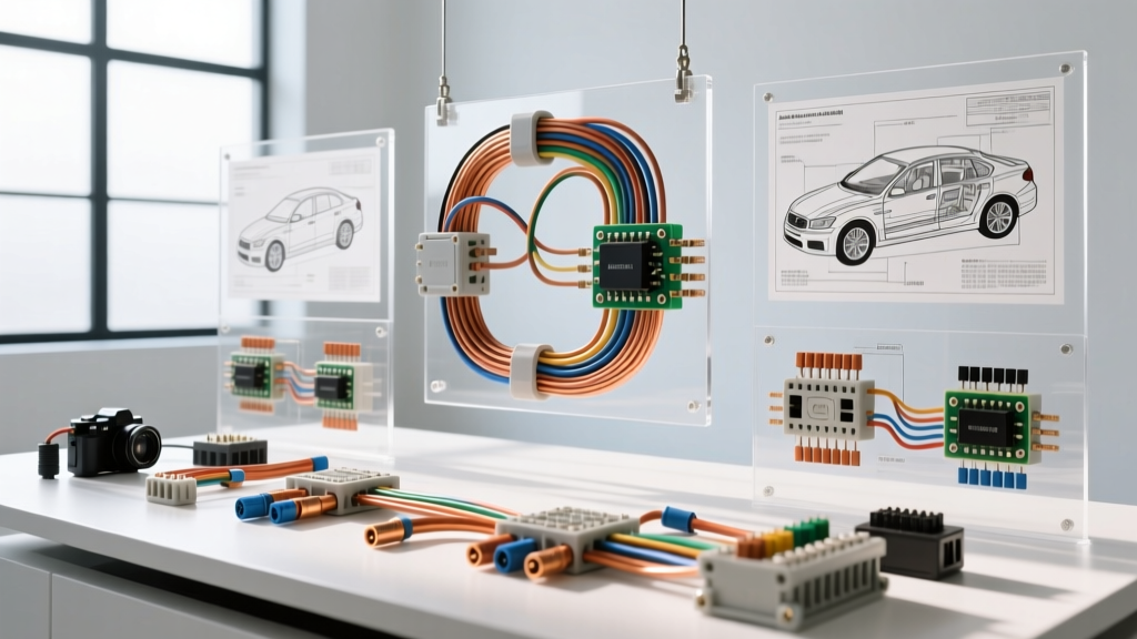
The Benchmark of Professional Auto Electrical Work
When tackling complex vehicle electrical architectures, custom builds, and classic car restorations, the margin for error is virtually zero. In the specialty automotive industry, the meticulous methodologies championed by historic and boutique specialists—often referenced under the benchmark of Masonic Auto Electric standards—represent the gold standard for multi-circuit reliability, auxiliary lighting integration, and parade vehicle electrical safety. Replicating this level of professional auto-electric work requires more than just connecting wires; it demands a deep understanding of load calculation, voltage drop mitigation, and strict adherence to safety protocols.
DIY enthusiasts and novice technicians frequently make critical errors when attempting to upgrade alternators, install high-draw auxiliary lighting, or rewire classic chassis. These mistakes can lead to melted insulation, parasitic draws, ECU failures, or catastrophic electrical fires. This guide outlines the most common wiring mistakes and essential safety warnings to ensure your vehicle's electrical system meets professional engineering standards.
Critical Safety Warnings Before Cutting or Splicing
Before any wire is stripped or terminal is crimped, specific high-risk circuits must be identified and isolated. Professional auto electricians adhere to strict color-code isolation protocols to prevent accidental deployment or shock hazards.
The SRS and Airbag Yellow Wire Rule
According to NHTSA safety guidelines and global automotive standards, any wire loom colored yellow indicates the Supplemental Restraint System (SRS) or airbag circuit. Never probe a yellow SRS wire with a standard digital multimeter (DMM). The internal battery of a standard DMM can output enough current to inadvertently trigger the squib in an airbag inflator, causing a lethal deployment. Always disconnect the negative battery terminal and wait a minimum of 15 minutes for the SRS backup capacitor to discharge before working near the steering column or A-pillars.
High-Voltage EV and Hybrid Isolation
In modern hybrid and electric vehicles, orange cabling denotes high-voltage (HV) circuits ranging from 400V to 800V. These circuits require specialized insulated tools, Class 0 rubber insulating gloves, and a verified lockout/tagout (LOTO) procedure at the manual service disconnect (MSD). Never attempt to splice, probe, or reroute orange HV cables.
Common Mistake 1: Ignoring Voltage Drop in High-Draw Auxiliary Circuits
One of the most frequent errors in custom builds—such as Shriner parade vehicles or off-road rigs—is sizing wire based solely on amperage capacity while ignoring the length of the wire run. Copper has inherent resistance. As wire length increases, voltage drops. If a 12V accessory receives only 10.5V due to excessive resistance, it will draw higher amperage to compensate, generating excess heat and potentially melting the wire insulation.
The SAE International J1128 Standard recommends a maximum voltage drop of 3% (0.36V on a 12V system) for critical circuits. When wiring a 40A off-road light bar located 15 feet from the battery (30 feet total round-trip including the ground), using 10 AWG wire will result in a severe voltage drop. You must step up to 6 AWG or 8 AWG wire to maintain system efficiency and safety.
SAE J1128 Wire Gauge and Ampacity Reference Chart
Use the following reference chart to select the correct Cross-Linked Polyethylene (XLPE) automotive wire (GXL/TXL) for your circuits. Note that these ratings assume a maximum ambient under-hood temperature of 125°C (257°F).
| AWG Size | Max Continuous Amps | Ohms per 1,000 ft (Copper) | Common Application |
|---|---|---|---|
| 18 AWG | 6A | 6.385 Ω | ECU sensors, low-draw LED indicators |
| 14 AWG | 15A | 2.525 Ω | Interior lighting, radio memory, horn |
| 12 AWG | 20A | 1.588 Ω | Fuel pumps, power windows, cigarette lighter |
| 10 AWG | 30A | 0.998 Ω | A/C blower motors, auxiliary 12V sockets |
| 8 AWG | 40A | 0.628 Ω | High-draw light bars, winch solenoids |
| 4 AWG | 100A | 0.248 Ω | Alternator main charge wire, inverter feeds |
| 1/0 AWG | 150A+ | 0.098 Ω | Battery to starter motor, main chassis ground |
Common Mistake 2: Daisy-Chaining Grounds and Poor Chassis Prep
Modern vehicles utilize a unibody or isolated body-on-frame architecture where the chassis serves as the common ground return path. A pervasive mistake is "daisy-chaining" multiple accessory grounds to a single 1/4" chassis stud. This creates a bottleneck, leading to ground loops, alternator whine in the audio system, and erratic ECU behavior.
The Professional Fix: Implement a star-grounding topology. Run individual ground wires from each high-draw accessory back to a centralized, heavy-duty grounding busbar or a dedicated chassis stud. When attaching a ground ring terminal to the chassis, you must remove all paint, powder coating, and rust down to bare steel using a wire brush or sanding disc. Apply a dielectric grease or zinc-rich cold galvanizing compound over the terminal after torquing it to spec to prevent oxidation, which acts as an electrical insulator and causes voltage drop over time.
Common Mistake 3: Incorrect Relay Pinouts and Missing Flyback Diodes
When adding high-current loads like auxiliary cooling fans or fuel pumps, a standard ISO mini relay is mandatory to prevent melting the dashboard switch. However, miswiring the relay pins or ignoring inductive kickback destroys sensitive solid-state switching modules.
Standard ISO Mini Relay Pin Configuration
- Pin 30: Constant 12V+ Power (from battery via main fuse)
- Pin 87: Normally Open (NO) Output to the Load (e.g., cooling fan)
- Pin 86: Relay Coil 12V+ Trigger (from ignition or dashboard switch)
- Pin 85: Relay Coil Ground (to chassis or ECU switched ground)
- Pin 87a: Normally Closed (NC) - Unused in standard high-draw setups
The Flyback Warning: When the relay coil (pins 85 and 86) is de-energized, the collapsing magnetic field generates a high-voltage reverse spike (inductive kickback) that can exceed 100V. If Pin 86 is triggered by an ECU driver or a solid-state timer, this spike will instantly fry the internal transistor. Always solder a 1N4001 clamping diode across pins 85 and 86, with the diode's cathode (the silver stripe) pointing toward Pin 86 (the 12V+ trigger side). This safely recirculates the voltage spike back into the coil.
Common Mistake 4: Using Non-Automotive Wire and Solder-Only Joints
Hardware store THHN building wire or standard PVC-jacketed stranded wire is entirely unsuitable for automotive environments. Standard PVC insulation becomes brittle when exposed to under-hood ozone, UV light, and 120°C+ ambient temperatures, leading to short circuits against the chassis. According to SEMA Garage Wiring Best Practices, only automotive-grade cross-linked polyethylene (XLPE) wire, specifically GXL, TXL, or SXL, should be used. These insulations resist melting when touched by a soldering iron and withstand extreme under-hood heat.
Furthermore, relying solely on solder for mechanical connections in high-vibration environments is a critical failure point. Solder creates a rigid, brittle joint that will eventually fatigue and snap under engine harmonics. The industry standard—mandated by Bosch Automotive Electrics guidelines—is to use an open-barrel or closed-barrel mechanical crimp using a ratcheting crimper, followed by an adhesive-lined, dual-wall heat shrink tube to seal out moisture and prevent capillary action from drawing water into the copper strands.
Final Inspection and Load Testing Protocols
Before buttoning up the interior or closing the hood, a professional auto electrician performs a comprehensive voltage drop test under load. Using a DMM, measure the voltage directly at the battery terminals while the engine is running and all new auxiliary loads are engaged. Then, measure the voltage at the furthest accessory terminal. If the difference exceeds 0.36V (3%), the wire gauge is too small, or a connection point has excessive resistance.
Additionally, utilize a thermal imaging camera to scan fuse boxes, ground studs, and relay terminals after 15 minutes of continuous operation. Any terminal glowing hotter than the surrounding wire indicates a high-resistance micro-short or a failing crimp. By adhering to these rigorous safety warnings and avoiding common architectural mistakes, you ensure a vehicle electrical system that is not only functional but exceptionally safe and reliable for decades of service.