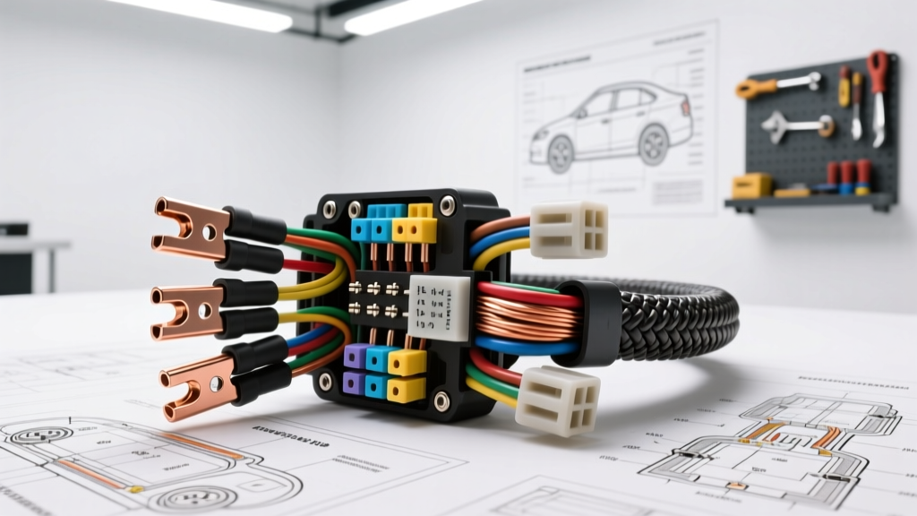
Introduction to Moore's Auto Electrical Standards
When engineering custom wiring harnesses for heavy-duty trucks, marine applications, and high-output automotive builds, selecting the correct terminals and connectors is critical for long-term reliability. Moore's Auto Electrical components have become a benchmark in the industry for high-retention force terminals, robust weather-sealed connectors, and tinned copper lugs designed to resist galvanic corrosion. This technical specification reference details the exact AWG mappings, crimp standards, weatherpack pinouts, and circuit integration guidelines required when utilizing Moore's Auto Electrical hardware in 12V and 24V vehicle architectures.
Unlike standard consumer-grade blister-pack terminals, Moore's heavy-duty line adheres strictly to SAE J1128 low-tension primary cable standards and SAE J1113 electromagnetic compatibility guidelines. Proper application of these components requires precise tooling, correct cavity sealing, and strict adherence to torque specifications to prevent voltage drop and thermal runaway under high-amperage loads.
Heavy-Duty Ring and Spade Terminal Specifications
The foundation of any high-current automotive electrical system lies in the battery-to-starter and alternator-to-battery connections. Moore's Auto Electrical offers both non-insulated tinned copper lugs and PVC/nylon-insulated crimp terminals. For engine bay applications where ambient temperatures exceed 105°C, non-insulated tinned copper lugs paired with adhesive-lined heat shrink (dual-wall polyolefin) are mandatory to prevent insulation melt and subsequent short circuits.
Terminal Sizing and Pull-Out Force Matrix
| AWG Size | mm² Equiv. | Stud Size | Barrel Length | Min. Pull-Out Force | Typical Application |
|---|---|---|---|---|---|
| 4/0 AWG | 107.2 mm² | 3/8" / M10 | 38.0 mm | 450 lbs (2000 N) | Main Battery to Starter Solenoid |
| 2/0 AWG | 67.4 mm² | 3/8" / M10 | 34.0 mm | 380 lbs (1690 N) | High-Output Alternator B+ (200A+) |
| 1/0 AWG | 53.5 mm² | 5/16" / M8 | 30.0 mm | 320 lbs (1420 N) | Secondary Battery Ground / Inverter |
| 4 AWG | 21.1 mm² | 5/16" / M8 | 22.0 mm | 240 lbs (1060 N) | Winch Power Feed / Heavy Duty Relays |
| 8 AWG | 8.37 mm² | 1/4" / M6 | 16.0 mm | 160 lbs (710 N) | Standard Alternator B+ Output |
Torque Specifications: When securing Moore's tinned copper lugs to battery posts or starter solenoids, proper clamping force is essential to minimize contact resistance. For 5/16" (M8) studs, apply 12-15 Nm. For 3/8" (M10) studs, apply 20-25 Nm. Always use a Belleville (conical) spring washer under the nut to maintain clamping force as the copper expands and contracts under thermal cycling.
Weatherpack Connector Pinouts and Cavity Maps
For sensor networks, EFI harnesses, and alternator control circuits, Moore's Auto Electrical weather-sealed connectors provide IP67-rated protection against moisture and dust ingress. These connectors utilize silicone cavity plugs and secondary Terminal Position Assurance (TPA) locks to prevent terminal back-out during high-vibration operation. The standard blade widths are 2.8mm for circuits up to 15A and 4.8mm for circuits up to 30A.
6-Way Weatherpack Pinout: High-Output Alternator Control Harness
Below is the standard reference pinout for a 6-way Moore's sealed connector used in modern high-output alternator integrations (e.g., AD244 or Denso SC1 style internal regulators requiring external sensing and ignition triggers).
| Cavity Pin | Wire Color (SAE) | AWG | Function | Terminal Type |
|---|---|---|---|---|
| 1 | Red | 10 AWG | B+ Battery Sense (Direct to Battery +) | 4.8mm Female |
| 2 | White/Red Tracer | 16 AWG | Ignition 12V Trigger (Run/Start) | 2.8mm Female |
| 3 | Light Green | 18 AWG | Stator / Tachometer Output Signal | 2.8mm Female |
| 4 | Black | 12 AWG | Regulator Ground (Clean Chassis) | 4.8mm Female |
| 5 | Yellow | 18 AWG | PCM LIN Bus / PWM Control Signal | 2.8mm Female |
| 6 | N/A (Plug) | N/A | Cavity Seal Plug (Unused) | Silicone Dummy |
Sealing Protocol: Every used cavity must have the silicone wire seal slid over the insulation jacket *before* crimping. The seal must sit flush against the terminal crimp shoulder. Unused cavities, such as Pin 6 in the diagram above, must be filled with a solid silicone cavity plug to maintain the IP67 pressure seal and prevent moisture from wicking into the harness via capillary action.
Crimping Standards and Tooling Matrix
Moore's Auto Electrical terminals require precise deformation to ensure a gas-tight connection. A gas-tight crimp prevents oxygen from reaching the copper strands, thereby eliminating galvanic corrosion inside the barrel. Use a ratcheting crimp tool calibrated to the specific terminal series. For PVC-insulated terminals, the tool must crimp the wire barrel and the insulation grip simultaneously without piercing the PVC sleeve. For open-barrel stamped terminals used in weatherpacks, the tool must form a distinct 'F' or 'B' fold, achieving a crimp compression ratio of 15-20% relative to the raw wire diameter.
12V vs 24V Alternator and Starter Circuit Integration
When adapting Moore's Auto Electrical harnesses for 24V heavy-duty truck architectures (such as Class 8 tractors or military HMMWVs), wire gauge sizing and insulation thickness must be recalculated. While 24V systems draw half the amperage for the same wattage (allowing for smaller AWG wires), the dielectric insulation must be rated for higher voltage spikes, which can exceed 60V during load-dump events.
- Insulation Rating: Ensure all Moore's TXL or GXL cross-linked polyethylene wire used in 24V systems is rated for a minimum of 60V DC (standard automotive wire is often rated for 50V). SXL insulation is preferred for its thicker wall and higher abrasion resistance.
- Starter Solenoid Wiring: In 12V systems, a 12 AWG wire is standard for the starter solenoid trigger. In 24V systems utilizing series-parallel battery banks, the trigger circuit must be isolated from the 24V return path. Use a 14 AWG wire with a dedicated 10A relay, triggered by a Moore's heavy-duty 30A micro-relay in the cab.
- Voltage Drop Thresholds: According to SAE standards, the maximum allowable voltage drop for a 12V starter circuit is 0.5V total. For a 24V starter circuit, the threshold is 1.0V total. When testing a Moore's harness, measure voltage drop *across the crimp joints and connectors* under load, not just end-to-end. A drop exceeding 0.1V across a single Moore's tinned lug indicates an improper crimp or oxidized mating surface.
Troubleshooting Voltage Drop in Moore's Harnesses
Even with premium components, installation errors can lead to parasitic voltage drops and thermal failures. Use the following decision tree when diagnosing issues in harnesses built with Moore's Auto Electrical components:
Symptom: Alternator B+ Terminal Overheating / Melting Insulation
- Cause 1: Improper crimp depth on the 8 AWG or 4 AWG ring terminal. Fix: Section the crimp with a bandsaw to verify strand deformation. Recrimp using the correct die cavity and verify pull-out force.
- Cause 2: Missing Belleville washer on the alternator B+ stud, leading to thermal loosening over time. Fix: Remove nut, clean terminal faces with a brass wire brush, apply dielectric grease to the *outside* of the joint (never between mating surfaces), and reinstall with a conical spring washer torqued to 12 Nm.
Symptom: EFI Sensor Intermittent Drop-Out over Bumps
- Cause 1: Missing Terminal Position Assurance (TPA) lock in the weatherpack connector. Fix: Depress the terminal release tab, extract the terminal, install the correct color-coded TPA lock, and reseat the terminal until an audible click is felt.
- Cause 2: Wire insulation stripped too far back, allowing the bare copper to bottom out in the cavity and short against adjacent pins. Fix: Strip wire to exactly 4.0mm for 2.8mm terminals and 6.0mm for 4.8mm terminals. The brush of the wire strands should be visible just past the crimp shoulder, but not extending into the mating cavity.
Conclusion and Best Practices
Building a reliable automotive electrical system requires more than just connecting wires; it demands strict adherence to engineering specifications. By utilizing Moore's Auto Electrical terminals, respecting the AWG-to-stud sizing matrix, and following precise weatherpack sealing protocols, technicians can eliminate the most common failure points in custom vehicle wiring. Always validate your crimp quality with periodic pull-tests and verify circuit integrity via loaded voltage drop testing before finalizing any harness installation.