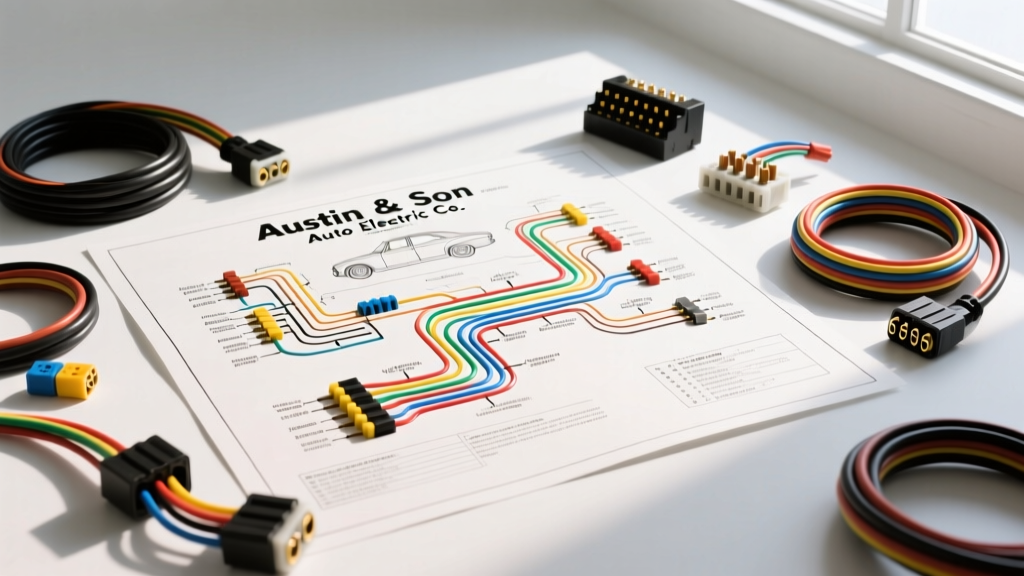
Decoding the Austin & Son Auto Electric Co Methodology
When approaching a complete vehicle rewire or a complex diagnostic trace, relying on a systematic methodology is the difference between a reliable electrical system and a rolling fire hazard. The archival standards and routing practices championed by legacy institutions like the Austin & Son Auto Electric Co represent the gold standard for complete wiring diagram walkthroughs. Rather than simply plugging connectors into a bulkhead, a true walkthrough requires tracing the architecture from the battery post to the furthest taillight filament, verifying gauge adequacy, voltage drop tolerances, and ground topology at every node.
In this comprehensive guide, we will execute a complete wiring diagram walkthrough using classic American V8 architecture (specifically 1960s-1970s GM and Ford platforms) as our baseline. We will dissect firewall bulkheads, ignition matrices, and lighting circuits, applying the rigorous verification standards that defined the Austin & Son Auto Electric Co approach to custom harness fabrication and restoration.
Phase 1: Firewall Bulkhead and Main Power Distribution
The firewall bulkhead connector is the central nervous system of any classic vehicle. In a standard GM 34-pin or Ford 24-pass-through harness, the bulkhead separates the harsh underhood environment from the protected cabin. A proper walkthrough begins at the main power distribution block (PDB) or the horn relay busbar.
Main Battery Feed and Alternator Output
The primary battery feed entering the engine bay must be sized to handle the total continuous amperage of the vehicle, plus a 20% safety margin. For a classic vehicle running a 65-amp alternator, standard heater, and halogen headlights, the main feed should never be smaller than 8 AWG. According to SAE J1128 standards for low-tension primary cable, an 8 AWG GXL (cross-linked polyethylene) wire can safely handle up to 70 amps in high-temperature engine bay environments.
- Battery to Starter Solenoid: 4 AWG or 2 AWG welding cable for minimal cranking voltage drop.
- Alternator Output to Busbar: 10 AWG (minimum) or 8 AWG (preferred for high-output 100A+ 1-wire alternators).
- Main Cabin Feed (Horn Relay to Bulkhead): 10 AWG Red wire, protected by a 14 AWG fusible link at the starter solenoid.
Expert Note: The Austin & Son methodology dictates that fusible links must always be exactly four wire gauges smaller than the wire they protect. A 10 AWG main feed requires a 14 AWG fusible link. Never use standard blade fuses for main un-switched battery feeds in classic restorations; blade fuses lack the slow-blow thermal characteristics required to handle brief inductive spikes from starter solenoids.
Phase 2: Ignition Switch and Solenoid Circuit Walkthrough
The ignition switch is a high-current routing matrix. In classic GM column-key applications, the switch is mounted on the steering column and actuated by a rack and pinion gear. Misinterpreting the ignition schematic is the leading cause of accessory back-feed and starter grind.
Classic GM 4-Terminal Ignition Pinout
Below is the definitive reference table for the classic GM 4-post ignition switch, detailing the exact wire routing, color codes, and AWG requirements to ensure the starter solenoid receives a minimum of 9.6V during cranking.
| Terminal Post | Function | Standard Wire Color | AWG Spec | Walkthrough Verification |
|---|---|---|---|---|
| BAT | Constant 12V+ Input | Red | 10 AWG | Must read 12.6V at all times. Protected by fusible link. |
| IGN | Switched 12V (Run) | Pink | 12 AWG | Feeds HEI distributor (requires 12 AWG to prevent coil starve). |
| ACC | Accessory Power | Brown | 14 AWG | Hot in Run and Acc. Drops out during Start to save cranking amps. |
| ST | Start Signal | Purple | 12 AWG | Routes to starter solenoid 'S' terminal. Must carry 15A+ surge. |
Neutral Safety Switch Integration
When tracing the Purple (Start) wire from the ignition switch, the diagram walkthrough must account for the neutral safety switch (NSS) or clutch interlock. The Purple wire is interrupted at the NSS. If the vehicle cranks in gear, the NSS bypass is miswired, or the switch ground path (often through the transmission case) has failed due to paint or rust.
Phase 3: Exterior Lighting and the Dimmer Switch Matrix
Exterior lighting circuits draw significant amperage and are highly susceptible to voltage drop due to the length of the wire runs from the front fascia to the rear taillights. A standard sealed beam headlight draws roughly 65 watts on high beam (approx. 5.4 amps per bulb). With two headlights and a taillight circuit, the main headlight switch feed can easily exceed 15 amps.
Floor-Mounted Dimmer Switch Routing
The classic floor-mounted headlight dimmer switch utilizes a simple 3-terminal configuration. During a diagram walkthrough, verify the following routing:
- Terminal 1 (Input): 12 AWG Light Blue wire from the headlight switch.
- Terminal 2 (Low Beam Output): 12 AWG Tan wire, splitting to both low-beam filaments.
- Terminal 3 (High Beam Output): 12 AWG Light Green wire, splitting to both high-beam filaments and the dashboard high-beam indicator bulb.
Upgrade Protocol: When restoring a vehicle using the Austin & Son Auto Electric Co standards, it is highly recommended to use the factory dimmer switch wiring only as a trigger circuit for a modern headlight relay harness. By routing the Tan and Light Green wires to the coils of 30-amp Bosch-style relays, you pull the heavy headlight amperage directly from the battery, eliminating the 2V-3V drop inherent in 50-year-old copper.
Phase 4: Grounding Architecture and Voltage Drop
A wiring diagram is only half the story; the ground topology is the invisible half of every circuit. Legacy auto electric shops understood that a 12 AWG ground wire is useless if it terminates to a painted surface. The Austin & Son methodology mandates a dedicated 'Ground Bus' approach for classic vehicles.
Grounding Specifications
- Engine to Chassis: 1/2-inch braided copper strap, minimum 100 amps capacity. Must attach to a bare, unpainted cast-iron boss on the block and a bare steel point on the frame.
- Body to Frame: 10 AWG black wire with star washers under the bolt heads to bite through sheet metal paint.
- Taillight Housings: Never rely on the housing bolts for ground. Run a dedicated 16 AWG black pigtail from the taillight socket ground ring directly to a localized ground bus bar in the trunk.
For deeper insights into classic grounding topologies and relay integration, the technical archives at Madelectrical provide excellent schematic overlays for upgrading vintage GM and Ford lighting grounds.
Diagnostic Walkthrough: Tracing a Dead Circuit
When a circuit fails to operate, do not immediately replace components. Execute this systematic voltage drop walkthrough to isolate the fault:
- Verify the Source: Set your multimeter to DC Volts. Place the black lead on a known good ground (battery negative) and the red lead on the power feed side of the component. You should read within 0.2V of battery voltage.
- The Voltage Drop Test: If the component has power but won't run, the ground is compromised. Leave the circuit turned ON. Place the red multimeter lead on the negative post of the battery, and the black lead on the metal casing of the component. A reading above 0.1V indicates high resistance in the ground path.
- Connector Pin Drag: If voltage is present at the wire but not the pin, the terminal crimp has failed. Use a Delphi Packard 50-series terminal extractor to remove the pin. Inspect the wire barrel. If the copper strands show green oxidation, the wire was stripped with nicked strands, capillary action drew moisture into the insulation, and the entire run must be replaced using TXL wire and a proper ratcheting crimp tool.
Summary of the Walkthrough Protocol
Performing a complete wiring diagram walkthrough requires discipline. By adhering to the rigorous standards of wire gauge selection, fusible link sizing, and dedicated grounding topologies pioneered by the Austin & Son Auto Electric Co, restorers and technicians can ensure that classic vehicles not only start reliably but remain safe and electrically stable for decades. Always consult manufacturer-specific schematics alongside Painless Performance classic wiring manuals to verify pinouts for your exact year, make, and model before applying power to a newly routed harness.