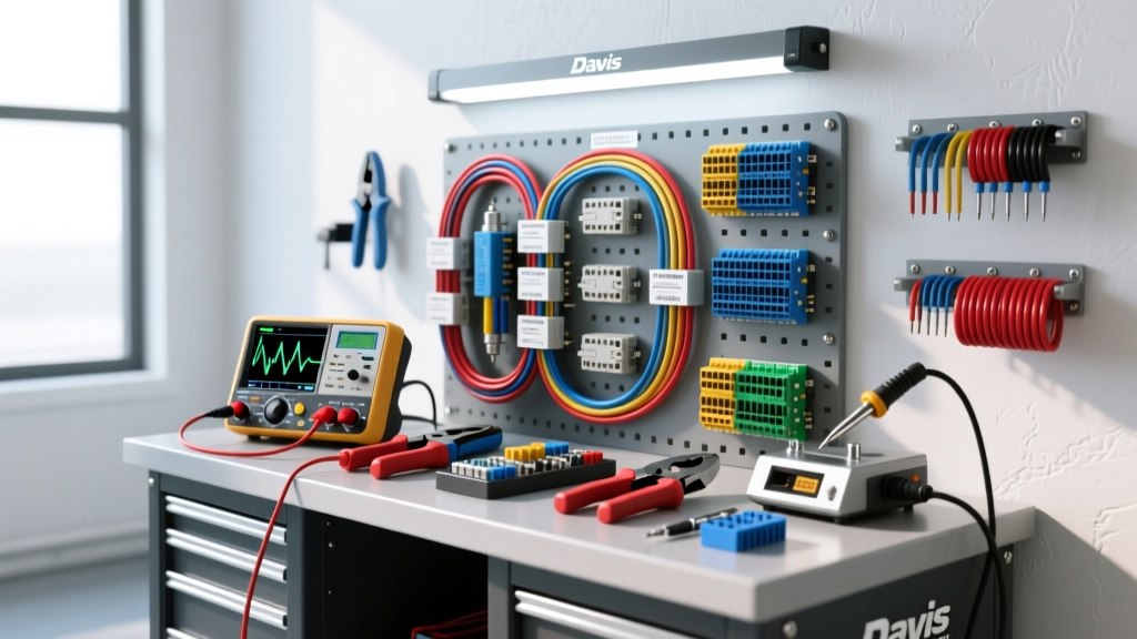
The Davis Auto Electrical Benchmark: Redefining the Diagnostic Bay
Modern vehicle electrical architecture has evolved from simple 12-volt analog circuits to complex, multiplexed networks utilizing high-speed CAN FD, LIN buses, and high-voltage EV systems. For independent repair shops and dedicated auto electricians, relying on basic test lights and entry-level multimeters is no longer viable. When benchmarking against the Davis Auto Electrical diagnostic methodology—a recognized standard for high-end, systematic electrical troubleshooting—the focus shifts toward precision, repeatability, and advanced signal analysis.
Replicating a Davis Auto Electrical setup requires a strategic investment in diagnostic hardware, specialized wiring tools, and thermal imaging equipment. This cost and tool requirements analysis breaks down the exact equipment needed to build a professional-grade auto electrical bench, detailing the technical specifications, real-world applications, and return on investment (ROI) for each category.
Core Diagnostic Hardware & Cost Breakdown
The foundation of any advanced electrical bay is the ability to measure, visualize, and manipulate electrical signals without damaging sensitive control modules. Below is the core hardware matrix required to meet professional diagnostic standards.
| Equipment Category | Recommended Tool / Spec | Est. Cost (USD) | Primary Application & Technical Spec |
|---|---|---|---|
| Automotive DMM | Fluke 88V (1000V DC, 10A) | $520 | PWM testing, duty cycle, frequency, and basic voltage drop. |
| Oscilloscope | PicoScope 4425A (4-Ch, 200MHz) | $2,250 | CAN bus decoding, injector waveforms, relative compression. |
| Circuit Tester | Power Probe IV (0-12V/24V) | $650 | Instant ground/power verification, 40ft reach, component actuation. |
| Thermal Imaging | FLIR E8-XT (320x240 Res) | $3,400 | Fuse box hotspot detection, high-resistance connection mapping. |
| Current Clamp | Pico TA018 (0-600A DC/AC) | $380 | Parasitic draw testing, starter inrush current analysis. |
| Sealed Crimper | Deutsch DT / Molex ML-XT Kit | $450 | 12-20 AWG sealed terminal crimping, weatherpack repairs. |
Total Estimated Baseline Investment: $7,650
Wiring, Terminals, and Crimping Standards
A critical pillar of the Davis Auto Electrical methodology is the refusal to use solder on high-vibration automotive harnesses. Solder wicks into wire strands, creating a rigid stress point that eventually fractures under chassis vibration. Instead, professional setups rely on gas-tight, cold-weld crimps using cross-linked polyethylene (XLPE) insulated wires like GXL and TXL.
AWG Sizing and Insulation Specs
When repairing a harness, matching the original equipment manufacturer (OEM) wire gauge and insulation thickness is mandatory. TXL (Thin-wall) and GXL (General cross-linked) wires operate safely up to 125°C and 150°C, respectively. A standard 16 AWG GXL wire has an outer diameter of approximately 2.3mm, making it ideal for most sensor circuits and CAN bus lines.
Crimp Pull-Out and Tooling Requirements
According to the IPC/WHMA-A-620 standard for cable and wire harness assemblies, a proper crimp must pass specific pull-out force tests. For a 16 AWG wire in a Deutsch DT series solid core pin, the minimum pull-out force requirement is 50 lbs (222 N). Achieving this requires a calibrated ratcheting crimper (such as the Deutsch 11-04-100) that ensures the wire barrel and insulation barrel are compressed to exact tolerances simultaneously. Furthermore, inserting the wedgelock (secondary retention clip) into the DT connector housing requires an audible click, ensuring the terminal will not back out when subjected to a 15 lb axial pull.
Oscilloscope Applications: CAN Bus & Alternator Ripple
The transition from multimeters to oscilloscopes is where the true diagnostic power of a Davis Auto Electrical bench is realized. Multimeters average voltage over time, completely missing microsecond glitches. Oscilloscopes graph voltage against time, revealing the true health of a circuit.
High-Speed CAN Bus Diagnostics
When diagnosing network communication faults, technicians must probe the OBD-II Data Link Connector (DLC). Pin 6 represents CAN-High, and Pin 14 represents CAN-Low. Following SAE J1939 and ISO 11898 guidelines, a healthy CAN network in a recessive (idle) state will show both lines resting at approximately 2.5V. When the network transitions to a dominant (active) state to transmit data, CAN-High rises to 3.5V while CAN-Low drops to 1.5V. An oscilloscope will instantly reveal if a module is pulling the bus low (short to ground), if there is excessive capacitance causing sloped waveform edges, or if a terminating resistor (nominally 60 ohms measured between Pin 6 and Pin 14 with the battery disconnected) has failed.
Alternator Ripple and Diode Trio Testing
Alternator output is rarely pure DC. The internal rectifier assembly converts AC stator output to DC, but a residual AC "ripple" remains. By connecting an oscilloscope or a DMM set to AC millivolts directly to the alternator B+ terminal (with the engine running at 2,000 RPM and electrical loads applied), a healthy system should display less than 50mV AC. If the ripple exceeds 100mV AC, it indicates a failed diode in the rectifier bridge or a shorted stator winding. This AC leakage can severely interfere with sensitive audio amplifiers and module logic boards, a fault easily missed without proper bench tooling.
Parasitic Draw and Thermal Imaging Analysis
Parasitic battery drain is one of the most time-consuming electrical complaints. The outdated method of pulling fuses one by one while watching a multimeter in series often causes modules to wake up, resetting the sleep cycle and yielding false readings.
Non-Intrusive Current Clamping
The modern standard utilizes a high-resolution DC current clamp (like the Pico TA018) placed over the negative battery cable. This allows the technician to monitor the vehicle's sleep cycle without breaking the circuit. A typical modern vehicle should drop below 30mA (0.030A) within 20 to 45 minutes. If a spike occurs, the oscilloscope can trigger on the current rise, allowing the tech to correlate the spike with LIN bus activity (OBD-II Pin 1) or specific module wake-up signals.
Thermal Imaging for High-Resistance Faults
Ohm's law dictates that resistance generates heat. When dealing with high-current circuits like starter motors, electric power steering (EPS), or cooling fan modules, a high-resistance connection will manifest as a thermal hotspot. A thermal camera with a resolution of at least 320x240 pixels can instantly identify a corroded M8 ground strap bolted to the chassis. While the torque spec for a typical M8 steel ground bolt to an aluminum chassis is 22 Nm (16 lb-ft), corrosion can increase resistance even if torque is correct. Thermal imaging allows the technician to spot a 15°C temperature delta across a fuse box busbar, pinpointing the exact failing relay or fuse leg without guessing.
ROI and Shop Integration
Investing over $7,500 in a Davis Auto Electrical standard bench setup may seem steep for a general repair facility. However, the ROI is realized through diagnostic efficiency and expanded service capabilities. A parasitic draw that once took 6 hours of manual fuse-pulling can be isolated in under 45 minutes using a current clamp and oscilloscope. Furthermore, the ability to perform definitive CAN bus diagnostics and module programming verification allows shops to keep high-margin electrical jobs in-house rather than subletting to dealerships.
For those looking to expand their diagnostic library, the Pico Technology Waveform Library provides thousands of known-good captures for alternators, sensors, and network buses, serving as an invaluable reference when comparing bench captures against OEM benchmarks. Ultimately, the cost of the tools is negligible compared to the cost of misdiagnosing a $1,500 control module due to a lack of proper signal visibility.