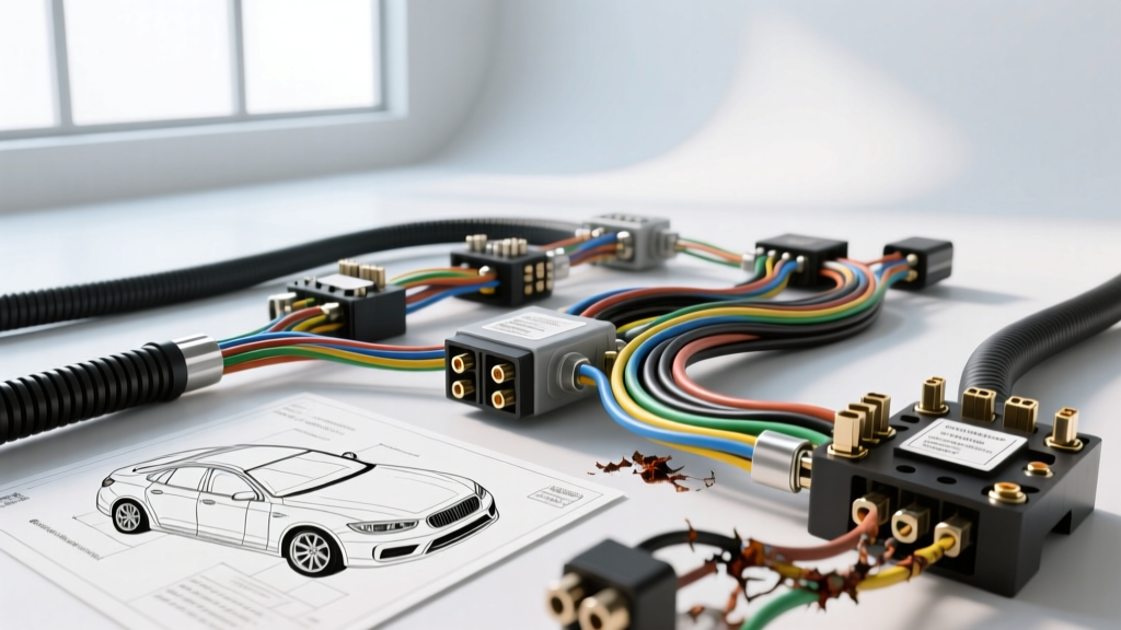
Introduction to Harness Diagnostics
When diagnosing intermittent parasitic draws, erratic sensor readings, or complete CAN-bus network failures, the root cause frequently traces back to the main car electrical harness. Modern vehicles contain over 2,000 individual circuits, spanning miles of copper wiring routed through high-vibration, high-heat, and moisture-prone environments. A generic 'check the fuses' approach is insufficient for modern automotive electrical architecture. Instead, technicians must employ a systematic, step-by-step car electrical harness troubleshooting flow to isolate voltage drops, micro-shorts, and terminal fretting. This guide provides a professional-grade diagnostic sequence, integrating multimeter testing, physical inspection protocols, and terminal-level pinout verification.
Phase 1: Physical Routing & Loom Degradation
Before introducing a digital multimeter (DMM) to the circuit, a rigorous visual and tactile inspection of the harness routing is mandatory. The most common failure points in any car electrical harness occur at transition zones where the wiring transitions from the static chassis to dynamic components like the engine block, steering column, or suspension subframe.
Key Inspection Zones:
- Bulkhead Pass-Throughs: Inspect the rubber grommets where the harness passes through the firewall. A degraded gromm allows water ingress, leading to capillary action where moisture wicks under the wire insulation, causing green copper oxide (verdigris) to form deep inside the loom.
- Exhaust Proximity: Check for heat shield degradation near exhaust manifolds. Standard split-loom tubing will melt at 225°F (107°C). If the harness is exposed, it must be re-wrapped using high-temperature Tesa 51036 PET cloth tape or fiberglass sleeving rated for continuous 300°F (149°C) exposure.
- Suspension Flex Loops: ABS wheel speed sensor harnesses and air-ride suspension pigtails endure constant articulation. Look for 'necking'—a visible thinning of the wire insulation indicating the internal copper strands have fractured.
Phase 2: Voltage Drop Testing (The Millivolt Method)
Resistance testing (Ohms) is notoriously inaccurate for diagnosing loaded automotive circuits because a single strand of 18 AWG wire can carry enough current to show 0.0 ohms on a DMM, yet fail under a 10-amp load. The SAE J1128 standard for low-voltage primary cable dictates that voltage drop under load is the only true measure of harness integrity.
Step-by-Step Voltage Drop Flow:
- Set the DMM: Switch your multimeter to the DC Millivolt (mV) scale. Auto-ranging meters can sometimes miss transient drops; manual ranging to the 200mV or 2V scale is preferred.
- Establish Baseline: With the circuit active (e.g., fuel pump running, starter cranking), place the red probe on the battery positive post and the black probe on the component's power feed pin.
- Evaluate the Drop: A healthy 10 AWG starter feed circuit should show no more than 0.2V (200mV) total drop. A 5V reference circuit to a MAP sensor should show less than 0.05V (50mV) drop. Anything higher indicates high resistance due to corrosion, undersized wire, or a failing bulkhead connector.
- Isolate the Segment: If the total drop is 0.8V, move the probes to test individual harness segments (e.g., Battery to Fuse Box, Fuse Box to Relay, Relay to Component) to pinpoint the exact failing node.
Phase 3: Connector & Terminal Micro-Fretting
According to TE Connectivity automotive terminal specifications, micro-fretting is a primary cause of intermittent sensor codes. Fretting occurs when low-current, high-vibration circuits (like oxygen sensors or camshaft position sensors) experience microscopic movement between the male and female terminals. This wears away the tin plating, exposing the underlying brass to oxidation, which acts as an insulator.
Terminal Extraction and Inspection:
Never probe the front of a sealed connector (like a Metri-Pack 280 or Weather-Pack) with standard test leads, as this spreads the terminal tangs and ruins the waterproof seal. Use proper terminal extraction tools (e.g., Lisle 37950 or specific Deutsch wedge removal tools) to back the terminal out of the housing. Inspect the mating surfaces for dark gray or black oxidation. If fretting is present, the terminals must be replaced—not merely cleaned—and coated with a specialized dielectric grease like Nyogel 760G, which is formulated to prevent fretting corrosion without interfering with low-current signal transmission.
Phase 4: Troubleshooting Decision Tree
Use the following diagnostic decision tree to rapidly isolate the specific failure mode within the car electrical harness based on your initial scan tool and DMM symptoms.
| Symptom / Scan Code | Initial DMM Test | Result / Observation | Root Cause & Repair Action |
|---|---|---|---|
| U0100 (Lost Comm with ECM) | Check CAN-H / CAN-L voltage to ground (Key On, Engine Off) | CAN-H is 0V, CAN-L is 0V (Normal is ~2.5V / ~2.5V) | CAN bus shorted to ground. Check harness chafing near steering column bracket. Repair using twisted-pair solder-sleeve. |
| P0131 (O2 Sensor Low Voltage) | Voltage drop test on O2 heater ground circuit (White/Black wire) | Drop reads 1.4V under load | High resistance at G110 (Left Cylinder Head Ground). Remove ring terminal, clean mating surface with Scotch-Brite (no wire wheels), and re-torque to 15 Nm. |
| Intermittent Stalling / No Crank | Wiggle test on main ignition relay feed while monitoring mV drop | Voltage spikes from 12.2V to 3.1V when harness is manipulated | Internal wire strand fracture inside the insulation near the bulkhead connector. Splice in new 12 AWG TXL wire using Raychem RT-1145 heat shrink. |
| Parasitic Draw (800mA after sleep) | Voltage drop across individual fuses (mV scale) | 15mV drop across 10A 'BCM/Infotainment' fuse | Module failing to sleep or harness short bypassing ignition switch. Pull module connector to isolate module vs. harness fault. |
Phase 5: Data Bus & Twisted Pair Integrity
Modern car electrical harness architecture relies heavily on high-speed CAN-bus networks. These circuits utilize unshielded twisted pair (UTP) wiring, typically 0.5mm² (20 AWG). The twisting is not arbitrary; it is engineered to maintain a precise 120-ohm impedance and cancel out electromagnetic interference (EMI) from the alternator and ignition coils.
Critical Repair Rule: When repairing a CAN-bus harness, you must maintain the twist rate (usually 20 to 30 twists per meter). Untwisting the wires more than 1 inch (25mm) at the splice point alters the impedance, causing signal reflection and resulting in cascading U-codes across multiple modules. Never use standard butt-connectors for data buses; always use high-temperature solder sleeves with integrated sealant rings to maintain the dielectric properties of the harness.
Phase 6: Wire Gauge (AWG) & Ampacity Reference
When replacing damaged sections of a car electrical harness, you must match or exceed the original equipment manufacturer (OEM) wire gauge and insulation type. Modern vehicles use Thin-Wall (TXL) or Cross-Linked (GXL) insulation, which allows for smaller outer diameters while maintaining high heat resistance compared to older PVC wires. Refer to the chart below for standard automotive harness specifications.
| AWG Size | Metric (mm²) | Max Continuous Amps (GXL/TXL) | Typical Harness Application | Common OEM Color Codes (Examples) |
|---|---|---|---|---|
| 18 AWG | 0.8 mm² | 10 Amps | 5V Reference, Sensor Signals, CAN-Bus | GM: Dark Blue (5V Ref) / Ford: White/Red |
| 16 AWG | 1.0 mm² | 13 Amps | Interior Lighting, Module Wake-up Lines | GM: Gray / Ford: Black/Pink |
| 14 AWG | 2.0 mm² | 20 Amps | Headlights, Power Windows, ABS Valves | GM: Yellow / Ford: Light Green/Purple |
| 12 AWG | 3.0 mm² | 28 Amps | Fuel Pump Feed, Starter Solenoid Trigger | GM: Gray/Black / Ford: Red/White |
| 10 AWG | 5.0 mm² | 40 Amps | Main Ignition Feeds, High-Amp Cooling Fans | GM: Red / Ford: Yellow/Light Green |
| 8 AWG | 8.0 mm² | 55 Amps | Alternator B+ Output, Main Battery Feed | GM: Red / Ford: Red |
Phase 7: Professional Splicing and Loom Restoration
The final step in the troubleshooting flow is executing a permanent repair. The Haynes Technical Tutorials and OEM service manuals universally condemn the use of 'twist and tape' methods or standard electrical tape for under-hood harness repairs. Electrical tape adhesive degrades at 180°F, unraveling and exposing the harness to moisture and debris.
The OEM-Approved Splice Protocol:
- Stripping: Use precision wire strippers calibrated for TXL thin-wall insulation to avoid nicking the copper strands. A nicked strand creates a stress riser that will snap under engine vibration.
- Crimping vs. Soldering: For high-vibration engine harnesses, an open-barrel crimp using a ratcheting tool (ensuring the proper bellmouth profile) is superior to soldering, which can create a brittle, rigid joint that snaps. For interior or static chassis harnesses, rosin-core soldering followed by adhesive-lined heat shrink is acceptable.
- Sealing: Slide a piece of dual-wall, polyolefin heat shrink (with internal meltable adhesive) over the wire before making the splice. Apply heat from the center outward to force the adhesive out the ends, creating a watertight environmental seal.
- Loom Wrapping: Re-wrap the repaired section using OEM-style Tesa cloth tape. Overlap the tape by 50% and stretch it slightly as you wrap to activate the pressure-sensitive adhesive, ensuring a tight, rattle-free finish that mimics the factory car electrical harness assembly.
Summary
Troubleshooting a complex car electrical harness requires moving beyond basic continuity checks. By combining systematic voltage drop testing, an understanding of terminal micro-fretting, and strict adherence to CAN-bus twisted-pair geometry, technicians can accurately isolate and permanently repair the most elusive electrical faults. Always reference the specific vehicle's wiring schematic for exact pinouts, ground locations, and wire color codes before cutting or splicing any harness segment.