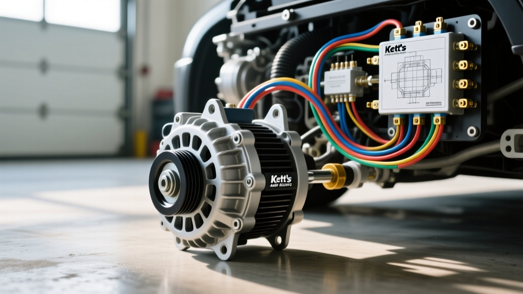
Understanding the Kett's Auto Electric 200A 1-Wire Architecture
When upgrading high-draw vehicle electrical systems for off-road lighting, heavy winching, or massive audio setups, sourcing reliable components is critical. Many fleet managers, expedition builders, and custom fabricators rely on Kett's Auto Electric for their heavy-duty, high-amperage alternator kits. Unlike standard OEM replacements that max out at 120 amps, the Kett's Auto Electric 200A high-output alternator is designed to sustain massive electrical loads at low engine RPMs. However, bolting on a 200-amp alternator is only half the battle; the real challenge lies in safely routing and terminating the heavy-duty charge harness to handle the immense current without creating a fire hazard or suffering from severe voltage drop.
The Kett's Auto Electric kit utilizes a 1-wire internal voltage regulator architecture. This means the alternator requires only a single heavy-gauge charge wire connected directly from the alternator's B+ output stud to the vehicle's battery positive terminal. While this eliminates the messy OEM sense and ignition wires, it requires strict adherence to SAE wiring standards to ensure the system self-excites properly and delivers clean, ripple-free DC voltage to your vehicle's sensitive electronics.
Essential Tools and Material Specifications
Before beginning the installation, ensure you have the correct materials. Using undersized wire or improper crimping tools is the leading cause of high-output alternator failures and electrical fires.
- Charge Wire: 1/0 AWG (0 AWG) SAE J1128 SGX fine-strand copper battery cable. Do not use CCA (Copper Clad Aluminum) wire, as it cannot handle the thermal load of 200 continuous amps.
- Overcurrent Protection: 250A ANL fuse and heavy-duty fuse holder.
- Terminals: 5/16-inch copper ring terminals, tinned, with adhesive-lined dual-wall heat shrink.
- Crimping Tool: Hydraulic hex-indent crimper. Avoid cheap dimple crimpers, which do not provide sufficient pull-out strength for 1/0 AWG cable.
- Hardware: Grade 8 M10x1.5 alternator mounting bolts, anti-seize compound, and dielectric grease.
- Testing Equipment: Digital multimeter (DMM) capable of measuring millivolts, and an inductive clamp meter for verifying amperage output under load.
Phase 1: Safely Decommissioning the OEM Charging System
Begin by disconnecting the negative battery terminal to isolate the chassis ground. Wait at least 15 minutes before proceeding to allow any high-capacity audio capacitors or airbag backup modules to discharge. Next, remove the OEM serpentine belt using a 1/2-inch breaker bar on the automatic belt tensioner pulley.
Unplug the OEM alternator harness. On most modern vehicles, this consists of a 2-pin or 3-pin connector containing the Ignition (IG), Sense (S), and Lamp (L) circuits. Carefully tape off these OEM connectors and secure them to the main harness using Tesa cloth tape to prevent them from rattling against the engine block. Remove the OEM B+ charge wire and unbolt the stock alternator. Clean the alternator mounting bracket ears on the engine block using a wire brush to ensure a flawless chassis ground path for the new Kett's Auto Electric unit.
Phase 2: Routing the 1/0 AWG SAE J1128 Charge Harness
Routing a 1/0 AWG cable requires careful planning. The cable must travel from the alternator's B+ terminal to the battery positive post, but it must avoid high-heat zones and moving components. According to the SAE J1128 SGX Battery Cable Standard, SGX insulation is rated for high-temperature engine bay environments, but direct contact with exhaust manifolds will eventually degrade the jacket.
- Measure the exact route from the alternator B+ stud to the battery positive terminal, adding 12 inches of slack for engine movement and service loops.
- Cut the 1/0 AWG cable using a heavy-duty ratcheting cable cutter to ensure a flush, square cut. Do not use bolt cutters, which deform the copper strands.
- Wrap the entire length of the cable in split-loom tubing, then secure the loom with high-temperature Tesa cloth tape. This provides abrasion resistance against aluminum brackets and firewall sheet metal.
- Route the cable along the inner fender well, securing it every 8 inches with UV-resistant nylon cable ties. Ensure the wire maintains a minimum 3-inch clearance from exhaust headers and steering linkage.
Phase 3: Alternator Mounting and Serpentine Belt Tensioning
Position the Kett's Auto Electric 200A alternator into the mounting bracket. Apply a small amount of copper anti-seize to the threads of the Grade 8 M10x1.5 mounting bolts to prevent galvanic corrosion between the steel bolts and the aluminum alternator housing. Torque the pivot bolt and the adjustment bracket bolt to 35 lb-ft using a calibrated torque wrench.
Install the new OEM-spec serpentine belt. Proper belt tension is critical; a 200-amp alternator places significant mechanical drag on the crankshaft pulley at peak output. Refer to the Gates Serpentine Belt Tensioning Guide to verify your automatic tensioner's indicator mark is within the acceptable green range. If using a manual V-belt setup on an older classic, apply 1/2-inch of deflection at the midpoint of the longest belt span under moderate thumb pressure.
Phase 4: Terminal Crimping and ANL Fuse Integration
Terminating 1/0 AWG wire correctly is non-negotiable. Strip exactly 7/8-inch of insulation from the cable ends. Slide a piece of adhesive-lined dual-wall heat shrink onto the cable before crimping. Insert the bare copper strands fully into the 5/16-inch copper ring terminal barrel.
Using a hydraulic hex-indent crimper, compress the terminal barrel. The hex-indent method cold-welds the copper strands and the terminal barrel together, creating a gas-tight connection that prevents moisture intrusion and resistive heating. Slide the heat shrink over the barrel-to-wire junction and apply heat until the adhesive sealant purges from the edges. Repeat this process for both the alternator end and the battery end.
Install a 250A ANL fuse in the charge circuit. The Littelfuse ANL Fuse Technical Datasheet specifies that ANL fuses provide excellent high-inrush current tolerance, making them ideal for alternator charge lines. Mount the ANL fuse holder on the positive battery terminal or within 7 inches of the battery post. This ensures the entire length of the 1/0 AWG cable is protected against dead-shorts to the chassis.
Kett's Auto Electric Wiring & Torque Specification Chart
| Component / Connection Point | Specification / Rating | Hardware / Tool Required |
|---|---|---|
| Alternator B+ Output Stud | 5/16" Ring Terminal, 200A Max | 10mm Deep Socket, Torque to 70 in-lbs |
| Main Charge Harness | 1/0 AWG SAE J1128 SGX Copper | Hydraulic Hex-Indent Crimper |
| Overcurrent Protection | 250A ANL Fuse (Non-Time Delay) | M8 Ring Terminals, 10mm Wrench |
| Alternator Pivot Bolt (M10x1.5) | Grade 8 Steel, Zinc Plated | Torque to 35 lb-ft |
| Alternator Adjustment Bolt | Grade 8 Steel, Zinc Plated | Torque to 35 lb-ft |
| Chassis Ground Path | Clean bare metal, < 0.05 Ohms | Wire Brush, Dielectric Grease |
Phase 5: System Excitation and Voltage Drop Testing
Reconnect the negative battery terminal. Start the engine. Because the Kett's Auto Electric alternator uses a 1-wire self-exciting regulator, it may not begin charging immediately at idle. Internal residual magnetism requires the alternator rotor to reach a specific RPM threshold—typically between 1,200 and 1,500 RPM—to 'kick in' and begin generating voltage. Briefly rev the engine to 2,000 RPM and hold it for three seconds. You should hear a distinct change in engine exhaust note as the mechanical load of the alternator engages, and your dashboard voltmeter should jump from 12.4V to 14.2V.
Once the system is charging, perform a voltage drop test across the entire charge circuit to verify the integrity of your crimps and wire routing. Set your digital multimeter to DC Volts. Place the red probe directly on the alternator B+ output stud and the black probe directly on the positive battery post. With the engine running at 2,000 RPM and electrical loads (headlights, blower motor, rear defroster) turned ON to force the alternator to produce at least 100 amps, the multimeter should read a maximum of 0.20 volts. If the reading exceeds 0.20V, you have excessive resistance in the charge wire, a poor crimp, or an undersized ANL fuse holder that must be corrected before the system is deemed safe for daily use.
Troubleshooting Low-RPM Self-Excitation Failure
A common characteristic of 1-wire high-output alternators is poor low-RPM charging. If your vehicle idles heavily in traffic and the battery voltage slowly drops below 12.8V, the alternator is failing to maintain self-excitation. While the Kett's Auto Electric kit is optimized for internal sensing, extreme low-RPM scenarios may require an external excitation wire.
If your specific Kett's model includes a secondary 'Excite' or 'Ignition' spade terminal, you can wire this to a switched 12V ignition source. Use 14 AWG TXL wire, routed through a 10A automotive relay triggered by the ignition switch. This provides a direct 12V bias to the internal voltage regulator the moment the key is turned to the 'Run' position, forcing the alternator to begin charging immediately at 600 RPM idle, bypassing the self-excitation RPM threshold entirely. Always consult the specific pinout diagram included with your Kett's Auto Electric unit before adding secondary ignition wiring to ensure you do not back-feed the internal regulator.