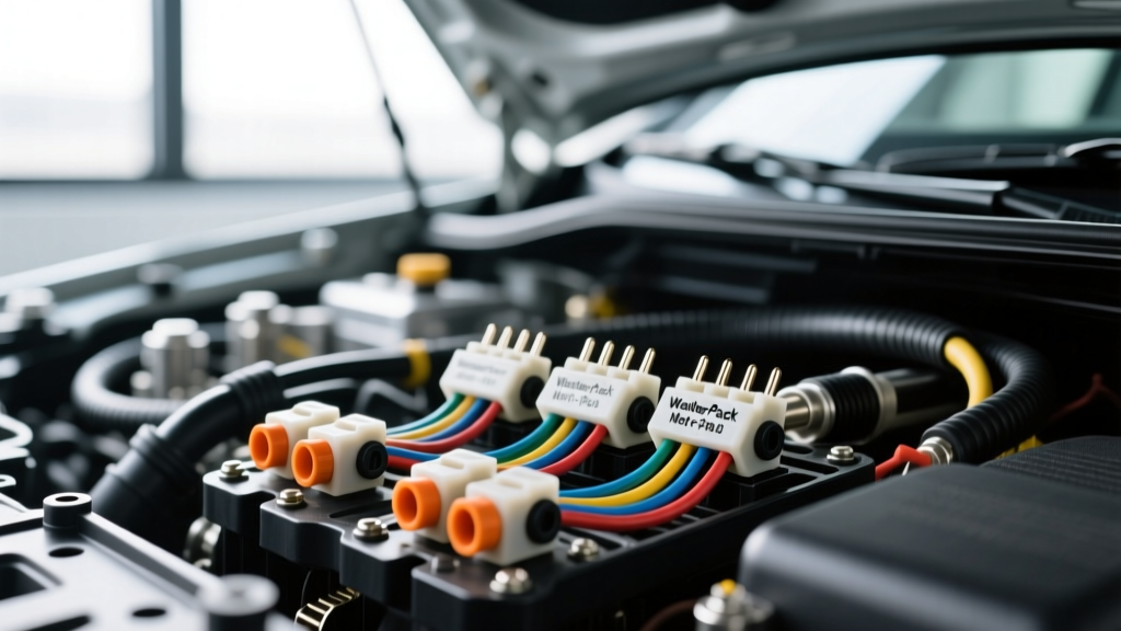
Introduction to Automotive Connector Integrity
When working on modern vehicle electrical architectures, from 12V CAN-bus networks to high-current EV systems, the physical integrity of the wiring harness is paramount. One of the most common points of failure introduced during DIY repairs or professional diagnostics is the damaged connector tab. Knowing exactly how to disconnect auto electrical connectors without breaking the primary latch, damaging the terminal position assurance (TPA), or causing terminal push-out is a fundamental skill for any automotive technician.
Automotive connectors are engineered to withstand extreme thermal cycling, high-frequency vibrations, and severe moisture exposure. To achieve this, manufacturers like TE Connectivity, Aptiv (formerly Delphi), and Molex utilize complex multi-stage locking mechanisms. Forcing a connector apart without understanding these mechanisms will inevitably result in broken plastic housings, backed-out terminals, and intermittent electrical faults that are notoriously difficult to diagnose.
Understanding Connector Anatomy and Locking Mechanisms
Before attempting to separate any harness plug, you must identify the specific locking architecture. Modern sealed connectors rely on up to three distinct retention systems:
1. The Primary Latch
The primary latch is the external plastic lever or tab that holds the male and female housings together. These are typically made of glass-filled nylon (PA66-GF) for heat resistance. They are designed to flex in one specific direction. Pulling the connector without depressing or lifting this latch will shear the tab off, rendering the connector useless without a zip-tie or secondary strap.
2. Connector Position Assurance (CPA)
Common in modern powertrain and safety systems (like airbag squibs and ABS wheel speed sensors), the CPA is a secondary external wedge, usually colored red, yellow, or bright green. The CPA slides into a channel on the housing, physically blocking the primary latch from being accidentally depressed. If you do not slide the CPA back to its 'unlocked' position first, the primary latch will not release.
3. Terminal Position Assurance (TPA)
The TPA is an internal secondary lock, often resembling a plastic comb or a sliding retainer block inside the rear of the connector housing. Its sole purpose is to prevent the metal terminals from pushing out the back of the housing if a wire is pulled. The TPA must be disengaged with a specialized pick tool before individual wires can be extracted (depinned).
Essential Tools for Safe Disconnection
Never use flathead screwdrivers or excessive brute force to separate automotive connectors. The following tools are mandatory for professional-grade harness work:
- Terminal Removal Tool Set: Includes flat blades for Metri-Pack, tubular extractors for Weather-Pack, and specialized hooks for AMP Superseal connectors.
- Plastic Pry Tools and Picks: Non-marring polymer picks to manipulate fragile CPA wedges and primary latches without scoring the glass-filled nylon.
- Electrical Contact Cleaner: A fast-evaporating solvent (like CRC QD Electronic Cleaner) to dissolve dielectric grease and light oxidation before disconnection.
- Dielectric Grease: For reapplication to the rubber environmental seals post-repair.
Step-by-Step: How to Disconnect Auto Electrical Connectors
Follow this precise sequence to safely separate sealed automotive connectors, whether you are working on a 35-pin ECM plug or a simple 2-pin oxygen sensor harness.
Step 1: Inspect and Clean the Exterior
Engine bays accumulate grease, road grime, and debris. Before touching the latch, spray the exterior of the connector with electrical contact cleaner and wipe it down. Debris trapped in the latch channel can act as an abrasive, snapping the plastic tab when you apply pressure. Inspect for any visible CPA wedges (red/yellow sliders) and slide them to the unlocked position.
Step 2: The Push-Pull Release Technique
The most critical technique in connector removal is the 'Push-Pull' method. Over years of heat cycling, the rubber environmental seal inside the connector compresses and bonds the two halves together. If you simply pull while pressing the latch, the tension on the plastic tab can cause it to snap.
- Push: Firmly push the two connector halves together. This relieves the mechanical tension on the primary latch caused by the compressed rubber seal.
- Press: While maintaining forward pressure, fully depress the primary latch. You should feel or hear a distinct click as the locking ramp clears the retention catch.
- Pull: While keeping the latch depressed, pull the connectors straight apart. Do not twist or rock the housing, as this can bend the delicate male terminal pins inside.
Step 3: Handling Stubborn or Fused Connectors
If the connector refuses to separate after the Push-Pull method, do not use pliers on the plastic housing. Instead, apply a small amount of penetrating oil (like PB Blaster or WD-40) directly to the mating seam. Allow it to wick into the rubber seal for 10 minutes. Gently wiggle the connector side-to-side by no more than 2 millimeters to break the seal bond, then repeat the Push-Pull method.
Technical Reference: Common Automotive Connector Families
Understanding the specific connector family dictates the tool and technique required for both disconnection and depinning. Below is a reference chart for the most prevalent systems in modern vehicles.
| Connector Family | Locking Mechanism | Typical AWG Range | Common Application |
|---|---|---|---|
| Delphi Metri-Pack 150 | Primary Latch + Internal TPA | 18 - 22 AWG | MAP, IAT, and Low-Current Sensors |
| Delphi Metri-Pack 280 | Primary Latch + TPA Comb | 14 - 18 AWG | Fuel Injectors, Ignition Coils, TPS |
| Delphi Weather-Pack | External Ramp Latch | 14 - 20 AWG | Older GM Lighting, Horns, Relays |
| TE AMP Superseal | Primary Latch + Red CPA | 16 - 20 AWG | European ECUs, Bosch Sensors |
| Deutsch DT / DTM | Internal Wedge Lock | 14 - 18 AWG | Heavy-Duty, Off-Road, J1939 Networks |
For deep technical specifications on heavy-duty network connectors, refer to the SAE J1939 Heavy-Duty Network Standards, which outlines the physical and environmental requirements for Deutsch-style connections in commercial vehicles.
Depinning: Extracting Individual Terminals
Sometimes, disconnecting the housing is only half the battle. If a specific wire is broken, or a terminal has suffered from galvanic corrosion, you must extract (depin) the individual terminal from the plastic housing. This requires disengaging the TPA and the terminal's internal retention barbs.
Extracting Metri-Pack Terminals
Metri-Pack terminals feature two small, outward-facing metal barbs that catch on a plastic shelf inside the housing. To remove them:
- Use a small plastic pick to lift the TPA comb out of its locked groove.
- Insert a specialized flat-blade terminal removal tool into the front (mating side) of the connector cavity, straddling the terminal.
- Push the tool in until you feel it depress the metal barbs inward.
- While holding the tool in to keep the barbs depressed, gently pull the wire from the rear of the housing.
Extracting Weather-Pack Terminals
Weather-Pack terminals utilize a different retention method. You must insert a tubular extraction tool over the pin from the front to collapse the retention springs. For comprehensive engineering drawings on these retention systems, the Aptiv Automotive Connection Systems Documentation provides exact tooling profiles and insertion/extraction force metrics.
Troubleshooting Corroded and Heat-Damaged Connectors
When disconnecting connectors in harsh environments, you will frequently encounter terminals coated in a green or white crust. This is copper oxide or galvanic corrosion, caused by moisture breaching the environmental seal and creating an electrolytic cell between dissimilar metals.
Assessing Terminal Damage
If the corrosion is strictly superficial (light green dusting), it can be cleaned using a fiberglass scratch pen or a brass-bristle brush. Never use steel brushes, as steel particles will embed in the copper alloy and accelerate future rusting. However, if the terminal plating (usually tin or gold over copper) is completely pitted, or if the male pin has reduced in diameter due to electrolysis, the terminal must be cut off and replaced. A pitted terminal will create high resistance, leading to voltage drops that can trigger false sensor codes, particularly on 5V reference circuits like throttle position sensors.
Dealing with Melted Housings
If the plastic housing is browned, brittle, or melted, this indicates severe resistance heating at the terminal interface. This is common in high-current circuits like radiator cooling fans or fuel pump modules where 14 AWG or 12 AWG wires carry 15-20 amps continuously. In these cases, simply disconnecting and reconnecting will not solve the issue. The entire connector pigtail must be spliced in using high-temperature solder and adhesive-lined heat shrink tubing, or ideally, a complete harness replacement.
Reconnection and Best Practices
Proper reconnection is just as vital as safe disconnection. Before mating the halves, inspect the male pins for any bending. A bent pin will scrape the female terminal's internal tension spring, permanently ruining the contact pressure.
The Role of Dielectric Grease
There is a pervasive myth in automotive forums that dielectric grease conducts electricity or should be packed inside the terminal cavities. This is false. Dielectric grease is an insulator. Its purpose is to lubricate the rubber environmental seal to prevent tearing and to exclude moisture from the connector body. According to TE Connectivity Automotive Connector Systems engineering guidelines, grease should be applied sparingly to the rubber seal and the exterior mating surface of the housing, not injected directly into the pin cavities, as it can trap debris and impede low-voltage signal transfer.
Verifying the Lock
Push the connector halves together until you hear a sharp, audible 'click'. This click is the primary latch snapping over the retention ramp. Once clicked, perform a gentle 'pull test' by tugging on the connector housings (not the wires) to ensure it is fully seated. Finally, if the connector is equipped with a CPA wedge, slide it fully into the locked position. This final step ensures that engine vibration will not slowly work the primary latch loose over thousands of miles of driving.