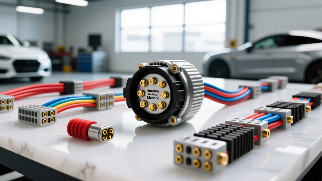
Introduction to Anahuac Auto Electric Heavy-Duty Standards
When engineering electrical systems for extreme environments—specifically the high-humidity, salt-spray, and hydrogen sulfide (H2S) conditions found in Gulf Coast oilfields and marine applications—standard automotive wiring rapidly degrades. The Anahuac Auto Electric methodology has become a benchmark reference for heavy-duty truck retrofits, LS-swapped marine vessels, and severe-duty agricultural equipment. This technical specification reference outlines the core wiring architecture, high-output alternator pinouts, and MIL-SPEC connector standards mandated by the Anahuac Auto Electric framework to ensure zero-failure electrical delivery in harsh operating environments.
Unlike standard passenger vehicle harnesses that prioritize cost and weight, the Anahuac Auto Electric standard prioritizes galvanic corrosion resistance, high-ampacity thermal management, and vibration-proof termination. The following specifications are derived from field-tested oilfield truck retrofits and heavy-duty marine repowers.
Core Wiring Architecture & Material Specifications
The foundation of any Anahuac Auto Electric compliant harness relies on strict adherence to marine-grade conductor standards. Standard PVC-insulated copper wire is strictly prohibited in primary power circuits due to its susceptibility to capillary action (wicking) when the insulation is breached.
Conductor Sizing and Insulation Requirements
- Insulation Type: All primary conductors must meet SAE J1128 TYPE SXL (Cross-Linked Polyethylene) specifications. SXL provides a continuous operating temperature rating of 125°C and superior resistance to abrasion and chemical exposure compared to standard GXL or TXL wire.
- Conductor Material: ASTM B33 Tinned Copper is mandatory for all chassis and engine bay routing. The tin plating prevents the formation of copper oxide and halts galvanic corrosion when exposed to saltwater or oilfield brine.
- Primary Power (B+): 1/0 AWG Red (SXL, Tinned) for alternator output and starter feeds up to 250A continuous.
- Heavy Cranking: 2/0 AWG Red (SXL, Tinned) for diesel applications requiring 800+ cold cranking amps (CCA).
- Sensor & Logic Circuits: 18 AWG to 16 AWG, utilizing twisted-pair configurations for CAN bus and critical ECU sensor signals to mitigate Electromagnetic Interference (EMI) from high-current PWM fuel pumps and electric AC compressors.
High-Output Alternator Pinout & Sense Wire Routing
The Anahuac Auto Electric standard heavily utilizes the Delco Remy 28SI and 40SI series high-output alternators (ranging from 160A to 300A) for heavy-duty applications. Proper excitation and voltage regulation require precise pinout adherence. A common failure mode in oilfield trucks is undercharging at low RPMs, which is almost always traced back to improper sense wire routing.
Delco Remy 28SI / 40SI Pin Configuration
| Terminal | Designation | Wire Color | AWG Size | Routing & Termination Specification |
|---|---|---|---|---|
| B+ | Battery Output | Red | 1/0 AWG | Route to main distribution busbar or battery positive. Use 3/8" tinned copper ring terminal. Torque to 120 in-lbs. |
| Pin 1 (L/I) | Lamp / Ignition | White | 14 AWG | Connects to dash warning indicator lamp, then to a switched 12V ignition source. Provides initial rotor excitation. |
| Pin 2 (S) | Voltage Sense | Yellow | 10 AWG | Critical: Must route directly to the battery positive post or main B+ busbar. Do NOT connect to the alternator B+ stud. Must be fused with a 5A AGC inline fuse within 7 inches of the battery. |
| Case | Ground | Black | 8 AWG | Dedicated braided ground strap from alternator case to engine block. Max resistance 0.01 ohms. |
According to Delco Remy Heavy Duty Alternator Service Guidelines, connecting the 'S' terminal locally to the alternator's own B+ output post defeats the purpose of remote sensing, causing the regulator to compensate only for local voltage and ignore the voltage drop occurring across the heavy-gauge chassis cables.
Starter Circuit & Solenoid Relay Logic
Heavy-duty diesel and big-block gas engines require massive cranking amperage. The Anahuac Auto Electric specification mandates the use of a remote starter solenoid (e.g., Cole Hersee 24063 continuous duty) to protect the ignition switch and reduce the length of the heavy-gauge positive cable running through the chassis.
Starter Wiring Matrix
- Battery to Remote Solenoid (Input): 2/0 AWG Red. Fused with a 500A Class-T fuse at the battery terminal.
- Remote Solenoid to Starter B+ (Output): 2/0 AWG Red. Kept as short as physically possible.
- Ignition Switch to Solenoid 'S' Terminal: 12 AWG Red/White stripe. This carries the low-amperage trigger signal (approx. 15A max inrush).
- Solenoid to Starter 'S' Terminal (Bypass): 14 AWG Yellow. Provides full battery voltage to the starter motor's internal solenoid during cranking, bypassing the factory ballast resistor circuit.
Voltage Drop Testing Limits: During a loaded crank test, the Anahuac standard dictates a maximum allowable voltage drop of 0.5V on the positive side (Battery Post to Starter B+ Stud) and 0.2V on the negative side (Starter Case to Battery Negative Post). Any reading exceeding these thresholds requires immediate cable replacement or terminal re-crimping.
Deutsch & Weather-Pack Connector Standards
In high-vibration environments, standard push-tab connectors will experience 'fretting corrosion'—a micro-arcing phenomenon caused by vibration breaking the oxide layer on the contact surfaces. The Anahuac Auto Electric framework mandates the use of Deutsch DT series or Amp Superseal 1.5 connectors for all under-hood and chassis accessories.
Deutsch DT Series Assembly Specifications
- Contact Sizing: 12-14 AWG wire requires Size 16 solid contacts. 16-18 AWG requires Size 20 contacts.
- Crimping Tool: Must use a closed-loop indenter crimper (e.g., Daniels M81969 or equivalent H-D Tool). Open-barrel crimpers are strictly prohibited for environmental seals.
- Wire Seals: Grey silicone wire seals must be pushed flush against the insulation jacket before crimping to ensure the rear cavity is completely waterproof.
- Wedge Locks (W12S / W12P): After inserting contacts into the connector housing until an audible 'click' is heard, the secondary wedge lock MUST be inserted. This prevents contact back-out when the harness is subjected to the harmonic vibrations of heavy-duty PTO (Power Take-Off) operations.
Grounding Architecture: Star vs. Daisy Chain
A critical differentiator in the Anahuac Auto Electric methodology is the strict prohibition of 'daisy-chain' grounding for any ECU, sensor, or low-amperage logic circuits. Daisy-chaining grounds (connecting Sensor A ground to Sensor B ground, then to the chassis) creates ground loops. When a high-current device (like an electric radiator fan or AC compressor clutch) cycles on, the voltage potential of the shared ground shifts, causing the ECU to read false sensor data.
Star Grounding Implementation
- All logic and sensor grounds (18-16 AWG Green wire) must be routed back to a single, centralized, isolated brass busbar.
- The busbar is then tied to the engine block or chassis via a single, heavy-gauge (4 AWG) tinned copper ground strap.
- Grounding lugs must utilize star washers to bite through paint and powder coating, ensuring bare metal-to-metal contact. Torque ground studs to 18 ft-lbs and coat with dielectric grease to prevent moisture ingress.
Troubleshooting Matrix: Common Heavy-Duty Electrical Faults
When diagnosing faults in systems built to these heavy-duty specifications, technicians should follow this symptom-cause-fix decision tree.
| Symptom | Root Cause Analysis | Anahuac Spec Corrective Action |
|---|---|---|
| Alternator outputs 13.8V at idle, but drops to 12.9V at high RPM under load. | Thermal protection mode activated due to poor case grounding or blocked cooling fins. | Verify alternator case ground strap (8 AWG). Clean mounting ears to bare metal. Ensure debris shields are not blocking the rear cooling fan. |
| ECU throws intermittent MAP/TPS sensor codes during heavy vibration. | Fretting corrosion or ground loop interference on sensor reference ground. | Isolate sensor ground. Reroute 18 AWG Green wire directly to the central star-ground busbar. Apply dielectric grease to ECU connector cavities. |
| Starter clicks once, but engine does not crank. Battery tests at 12.6V resting. | Voltage drop across remote solenoid contacts or corroded B+ cable insulation wicking. | Perform loaded voltage drop test across solenoid. If >0.5V, replace solenoid. Inspect 2/0 AWG cable ends for green copper oxide; cut back and re-terminate with adhesive-lined heat shrink. |
| Auxiliary lighting relay coil burns out prematurely. | Inductive voltage spike from relay coil collapsing without a flyback diode. | Install a 1N4004 flyback diode across the relay coil terminals (cathode to positive, anode to negative) to absorb the inductive kickback. |
Conclusion and Maintenance Intervals
Adhering to the Anahuac Auto Electric technical specifications ensures that heavy-duty, marine, and oilfield vehicles maintain electrical integrity despite extreme environmental abuse. To maintain this standard, fleet operators and custom builders must implement a 6-month preventive maintenance schedule. This includes checking all B+ torque specs (retorque to 120 in-lbs), inspecting Deutsch wedge locks for seating depth, and performing loaded voltage drop tests on the starter and alternator sense circuits. For further reading on heavy-duty electrical system design and vibration resistance, refer to the SAE J1928 Heavy Duty Truck Electrical Systems guidelines and relevant MSHA electrical installation standards for severe-duty mobile equipment.