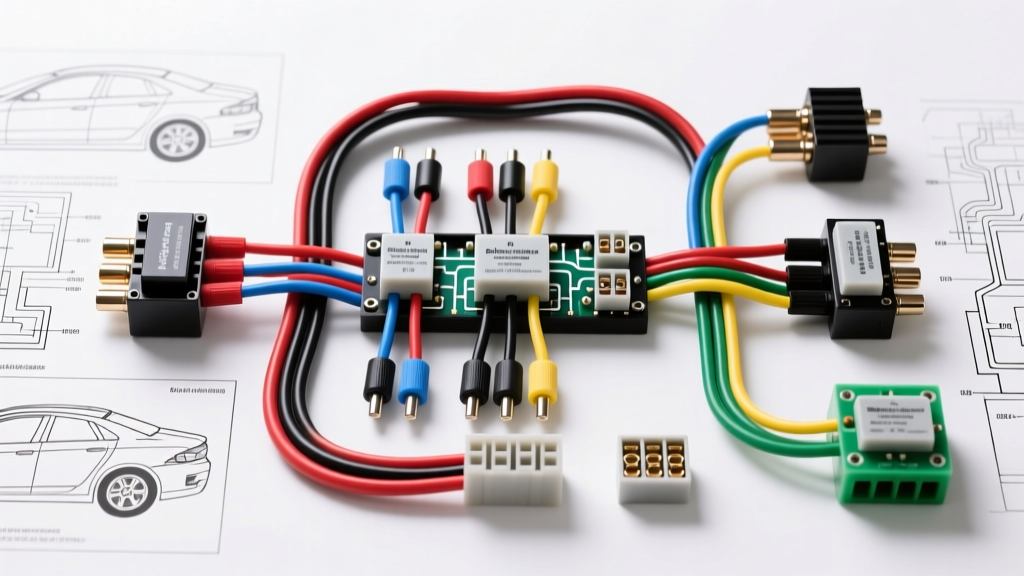
Introduction to the Shelby's Auto Electric Standard
When enthusiasts and professionals discuss benchmark automotive electrical repair, the phrase 'Shelby's Auto Electric' often evokes a standard of meticulous wiring, robust charging systems, and flawless grounds. Whether you are restoring a classic 1965 Shelby GT350, upgrading a daily driver, or simply trying to understand why your headlights dim at idle, mastering the fundamentals of auto electrical systems is non-negotiable. This beginner-friendly guide breaks down the core concepts of vehicle electrical architecture, decoding wiring diagrams, and executing reliable repairs using industry-standard specifications.
Core Concepts: Voltage, Current, and Resistance
Before cutting a single wire, you must understand the 'Big Three' electrical properties. Think of electricity like water flowing through a pipe:
- Voltage (Volts): The electrical pressure. A standard automotive system is nominally 12V, but when the engine is running and the alternator is charging, system voltage should read between 13.8V and 14.4V.
- Current (Amps): The volume of electrical flow. High-amperage circuits (like starter motors) require thick wires, while low-amperage circuits (like dashboard illumination) can use thin wires.
- Resistance (Ohms): The restriction to flow. Corroded connectors, undersized wires, and poor grounds create unwanted resistance, leading to voltage drops and component failure.
According to Haynes Automotive Electrical Basics, the most common cause of electrical gremlins in older vehicles is not a failed component, but excessive resistance in the wiring harness or grounding points.
Wire Sizing and AWG Standards
Using the correct American Wire Gauge (AWG) is critical. Undersized wires will overheat, melt insulation, and potentially cause electrical fires. The Society of Automotive Engineers outlines strict standards for low-tension primary cables in vehicles, as detailed in the SAE J1128 specification. Always size your wire based on the maximum amperage draw and the length of the run.
| AWG Size | Max Amperage (Chassis Wiring) | Common Automotive Application |
|---|---|---|
| 18 AWG | 10 Amps | Dashboard lights, ECU sensors, radio memory |
| 16 AWG | 13 Amps | Tail lights, turn signals, horn relay coil |
| 14 AWG | 15 Amps | Headlight low beams, power window switches |
| 12 AWG | 20 Amps | Fuel pumps, radiator cooling fans, cigarette lighter |
| 10 AWG | 30 Amps | High-output headlight relays, A/C blower motors |
| 8 AWG | 40 Amps | Alternator main charge wire (up to 80A alternators) |
| 4 AWG | 60+ Amps | Battery to starter solenoid, high-output alternators (100A+) |
Decoding Classic Ford and Shelby Wire Color Codes
If you are working on a classic Ford or Shelby Mustang, the factory wiring harness utilizes specific color codes with tracer stripes. Understanding these colors is essential for troubleshooting starter circuits and charging systems without relying solely on a faded schematic.
Classic Starter Solenoid Wiring
The classic Ford starter solenoid (mounted on the fender) is a frequent source of confusion for beginners. It features two large posts and two small threaded terminals ('S' and 'I').
- Battery to Solenoid (Large Post): 4 AWG Black (or Red in aftermarket kits). Constant 12V.
- Solenoid to Starter Motor (Large Post): 4 AWG Black with Yellow stripe. Only hot during cranking.
- 'S' Terminal (Start Signal): 12 AWG Red with Light Blue stripe. Receives 12V from the ignition switch only when the key is in the 'START' position.
- 'I' Terminal (Ignition Bypass): 14 AWG Brown wire. Sends 12V directly to the positive side of the ignition coil during cranking to ensure a hot spark while the ballast resistor is bypassed.
Demystifying Relays: The 4-Pin and 5-Pin Standard
A relay is an electrically operated switch. It allows a low-current circuit (like a headlight switch) to control a high-current circuit (like the headlights themselves), preventing the switch from melting. The industry standard is the Bosch-style ISO relay.
Bosch-Style Relay Pin Configuration
| Pin Number | Function | Connection Target |
|---|---|---|
| 85 | Coil Ground | Vehicle chassis ground |
| 86 | Coil Power | Switched 12V from dashboard switch or ECU |
| 30 | Common Input | Constant 12V from battery (via fuse/breaker) |
| 87 | Normally Open (NO) | Power output to the high-draw load (e.g., headlights) |
| 87a | Normally Closed (NC) | Power output when relay is OFF (used for 5-pin changeover setups) |
Pro-Tip: When installing relays for auxiliary off-road lights or fuel pumps, always place a diode or a resistor across pins 85 and 86 to suppress the inductive voltage spike that occurs when the relay coil collapses. This protects sensitive ECUs and switches from arc damage.
Upgrading the Charging System: 1-Wire vs. 3-Wire Alternators
One of the most common upgrades performed in the spirit of Shelby's Auto Electric standards is replacing a weak, factory 1-wire or early 3-wire alternator with a high-output modern unit. Understanding the difference is crucial for a stable electrical system.
The 1-Wire Alternator
A 1-wire alternator only requires a single heavy-gauge charge wire connected from the alternator output terminal directly to the battery positive post. While installation is simple, 1-wire units often require the engine to be revved to 1,500+ RPM to 'excite' the internal regulator and begin charging. They also sense voltage at the alternator case, not the battery, which can lead to undercharging if the main battery cables have slight resistance.
The 3-Wire Alternator (The Superior Choice)
For vehicles with heavy electrical loads (EFI, electric cooling fans, high-wattage audio), a 3-wire setup is mandatory. As outlined by the charging system experts at MAD Electrical, a 3-wire system uses a remote voltage sense wire to ensure the battery receives exactly 14.2V, regardless of voltage drop in the main harness.
Classic Ford 3G Alternator Wiring:
- Main Output (BATT): 4 AWG or 8 AWG Black with Orange stripe. Runs directly to the battery positive or main starter solenoid post. Must be protected by a 150A Mega Fuse.
- Sense Wire (Yellow/Black): 16 AWG. Connects directly to the battery positive side of the starter solenoid to read true system voltage.
- Ignition/Lamp Wire (White): 16 AWG. Connects to a switched 12V ignition source to turn the internal regulator on.
- Stator/Communication (Green/Red): Connects to the instrument cluster charge indicator light.
The Importance of Proper Grounding
An electrical circuit is only as good as its return path to the battery. In classic steel-bodied vehicles, the chassis is used as the ground return. However, rust, paint, and polyurethane bushings interrupt this path.
To meet top-tier auto electric standards, you must establish dedicated ground straps. Use a minimum of 4 AWG braided copper strap to connect the engine block to the chassis, and the chassis to the battery negative terminal. For high-draw accessories like electric fuel pumps or audio amplifiers, never rely on chassis grounding; always run a dedicated 12 AWG or 10 AWG ground wire directly back to the battery negative terminal or a centralized, clean copper bus bar.
Essential Tools for the Beginner
To execute these fundamentals properly, your toolkit must include:
- Digital Multimeter (DMM): Essential for measuring voltage drop across connections. A healthy connection should show less than 0.1V drop under load.
- Ratcheting Wire Crimper: Never use pliers to crimp terminals. A ratcheting crimper ensures a gas-tight, cold-weld connection that resists vibration and moisture.
- Heat Shrink Tubing with Adhesive: Use marine-grade, adhesive-lined heat shrink (typically 3:1 shrink ratio) to seal out moisture and prevent green corrosion at the crimp joint.
By adhering to these fundamental principles—proper wire sizing, understanding relay logic, utilizing 3-wire charging systems, and establishing flawless grounds—you will build an automotive electrical system that is reliable, safe, and worthy of the highest professional standards.