The Tijerina Auto Electric Approach to 12V Systems
Entering the world of automotive electrical diagnostics can feel overwhelming for beginners. Modern vehicles contain miles of copper wiring, complex CAN bus networks, and sensitive control modules. However, the Tijerina Auto Electric foundational methodology strips away the intimidation by focusing on the universal constants of all 12-volt DC systems: Power, Ground, and Load. Whether you are troubleshooting a no-crank condition on a 1998 Chevy Silverado or upgrading the stereo system in a 2015 Honda Civic, mastering these beginner-friendly fundamentals is the key to accurate, efficient repairs.
The core philosophy of the Tijerina Auto Electric training standard dictates that 85% of all automotive electrical faults are not caused by failed components, but by high-resistance connections or inadequate wire sizing. By understanding how current flows, how to properly size conductors, and how to measure voltage drop, even a novice DIYer can diagnose complex circuit failures without resorting to the costly "throw parts at it" strategy.
The Big Three: Power, Ground, and Load
Every functional circuit in your vehicle requires three elements:
- Power Source: Typically the battery or alternator, providing the electrical pressure (voltage).
- Load: The component doing the work (e.g., headlight bulb, starter solenoid, fuel pump).
- Ground: The return path to the negative battery terminal, completing the circuit via the vehicle's steel chassis.
If a circuit fails, the Tijerina method requires you to verify the integrity of the power supply and the ground path before condemning the load itself.
Understanding SAE J1128 Wire Standards and AWG Sizing
One of the most critical mistakes beginners make is using household solid-core wire or undersized stranded wire for automotive repairs. Automotive environments are subjected to extreme heat, vibration, and chemical exposure. According to SAE International Standard J1128, low-tension primary cables used in vehicles must feature stranded copper cores with specific insulation types (like PVC, XLPE, or cross-linked polyethylene) rated for continuous temperatures up to 125°C or higher in engine bays.
Wire sizing is measured in American Wire Gauge (AWG). In the AWG system, a lower number indicates a thicker wire capable of carrying more amperage. Using a wire that is too thin for a given load will cause excessive resistance, leading to voltage drop, overheating, and potentially a melted harness or electrical fire.
Automotive Wire Gauge Reference Chart
| AWG Size | Max Amperage (Chassis) | Typical Automotive Application | Common Insulation Color |
|---|---|---|---|
| 1/0 AWG | 300A+ | Battery to Starter Motor main cable | Red or Black |
| 4 AWG | 120A | High-output alternator B+, Winch power | Red |
| 10 AWG | 40A | Standard alternator B+, Horn relay feed | Red or Yellow |
| 14 AWG | 15A | Headlight feeds, Fuel pump power | Blue or Green |
| 18 AWG | 7A | ECM sensor signals, Dash illumination | White, Pink, or Gray |
Note: Amperage ratings assume a standard 12V chassis environment with bundled wiring. Free-air ratings are higher, but bundling reduces heat dissipation.
Practical Application: Wiring the Delco 10SI Alternator
To apply the Tijerina Auto Electric fundamentals, let us examine one of the most common and widely swapped alternators in automotive history: the GM Delco 10SI. Understanding its pinout and wire gauge requirements is a rite of passage for auto-electric beginners.
The 10SI utilizes a simple 2-pin connector alongside a heavy-gauge B+ output stud. If you are wiring this into a custom harness or repairing a degraded factory plug, you must adhere to the following specifications:
- B+ Terminal: Requires a minimum of 10 AWG (or 8 AWG for longer runs) stranded copper wire with a 5/16" ring terminal. This wire routes directly to the battery positive or the main starter junction block.
- Pin 1 (L - Lamp/Excitation): Requires 18 AWG wire. This provides the initial excitation current to the voltage regulator. It is typically wired through a dashboard warning bulb (which provides the necessary resistance) or a 50-ohm resistor if using an LED dash light.
- Pin 2 (I - Ignition/Voltage Sense): Requires 18 AWG wire. This pin senses battery voltage to regulate the alternator's output. For optimal charging, especially in vehicles with heavy electrical loads, this wire should be routed directly to the battery positive or a clean ignition-switched 12V source.
Connector Identification: Metri-Pack vs. Weather-Pack
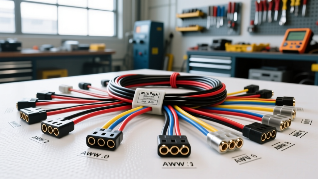
When repairing sensor pigtails or building custom harnesses, beginners must learn to identify OEM connector families. The two most prevalent in American and Asian vehicles are the Delphi (now Aptiv) Metri-Pack and Weather-Pack series.
- Metri-Pack 150 Series: Compact, sealed connectors used for low-current sensors (e.g., MAP, TPS, Coolant Temperature). The terminals are rated for up to 15 amps and typically accept 18 to 22 AWG wire.
- Metri-Pack 280 Series: Slightly wider, used for medium-current loads like fuel injectors, idle air control valves, and transmission solenoids. Rated for up to 22 amps.
- Weather-Pack: The older, bulkier cylindrical connectors common on 1980s and 1990s GM and Ford trucks. They feature large rubber seals and robust locking tangs, ideal for high-vibration areas like the transmission bellhousing or engine block.
Always use a dedicated ratcheting crimp tool (such as the Delphi Packard crimpers) when terminating these pins. Soldering wires directly to automotive terminals is discouraged by the Tijerina methodology, as solder wicks up into the stranded wire, creating a rigid point that will inevitably snap under engine vibration.
Voltage Drop Testing: The Ultimate Diagnostic Standard
The cornerstone of the Tijerina Auto Electric diagnostic tree is the Voltage Drop Test. Many beginners attempt to diagnose circuits by measuring resistance (Ohms) with the power disconnected. However, a multimeter's ohmmeter applies only a tiny fraction of a volt to test continuity. A single strand of 24 AWG copper wire can show 0.01 Ohms of resistance but will instantly melt if asked to carry 40 amps to a starter motor.
Voltage drop testing measures the circuit under load. As electrical current is forced through a poor connection, corrosion, or undersized wire, it encounters resistance. This resistance converts electrical energy into heat, resulting in a loss of voltage across the fault. According to Fluke Corporation's diagnostic guidelines, a healthy circuit should consume all available voltage at the load, leaving zero voltage on the supply and ground wires.
Step-by-Step Starter Circuit Voltage Drop Test
If your vehicle cranks slowly, do not immediately buy a new starter. Perform this test with your multimeter set to DC Volts:
- Prepare the Meter: Set your digital multimeter to the 20V DC scale.
- Test the Positive Side: Place the red probe directly on the battery's positive post (not the clamp, the lead post itself). Place the black probe directly on the starter motor's B+ terminal.
- Crank the Engine: Have an assistant crank the engine for 5 seconds. Observe the meter. A reading of more than 0.5V indicates excessive resistance on the positive side (corroded battery clamps, damaged internal strands in the 1/0 AWG cable, or a failing ignition switch).
- Test the Negative (Ground) Side: Place the red probe on the starter motor's metal casing (ensure bare metal contact). Place the black probe on the battery's negative post.
- Crank the Engine Again: A reading of more than 0.5V indicates a poor engine block ground or corrosion between the battery negative cable and the chassis.
- Test Individual Connections: To isolate the fault, move your probes across individual connections (e.g., from the battery clamp to the cable end). A single connection should never drop more than 0.1V during cranking.
By utilizing voltage drop testing, you can pinpoint a hidden corrosion issue inside a battery terminal or a frayed ground strap without ever unbolting a component. For further reading on testing charging systems once the engine is running, refer to the Haynes Alternator Testing Guide.
Conclusion: Building a Solid Electrical Foundation
Automotive electrical work is not dark magic; it is applied physics. By adopting the Tijerina Auto Electric fundamentals—respecting SAE wire gauge standards, utilizing proper ratcheting crimp tools for Metri-Pack connectors, and relying on voltage drop testing rather than guesswork—you transition from a parts-swapper to a true diagnostic technician. Always remember: electricity will always take the path of least resistance, and it is your job to ensure that path is clean, tight, and properly sized for the load.