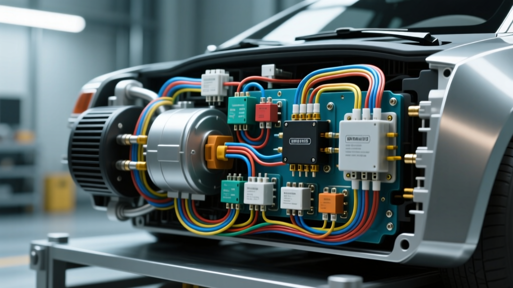
Introduction to Electric AC Compressor Diagnostics
Transitioning from a traditional engine-driven belt setup to an electric AC for cars is a hallmark of modern EV conversions, classic restomods, and heavy-duty auxiliary cooling systems. Unlike belt-driven compressors that rely on mechanical clutches, electric compressors utilize integrated inverters and brushless DC (BLDC) motors. While this eliminates parasitic engine drag, it introduces complex electrical architectures that require precise diagnostic workflows. When an electric AC system fails to engage, stutters, or throws an inverter fault code, the issue is rarely the compressor itself—it is almost always a wiring, voltage drop, or signal communication failure.
This guide provides a systematic, step-by-step troubleshooting flow for 12V and 24V high-amperage electric AC compressors (such as those from Dometic, Vintage Air, or Parker). We will bypass the guesswork and move directly into structured electrical diagnostics, focusing on wire gauges, pin configurations, and signal verification.
Safety and Prerequisites
Before probing any circuits, understand that electric AC compressors draw massive inrush currents. A typical 12V restomod electric compressor can pull 40 to 70 amps under peak load. Ensure your digital multimeter (DMM) is rated for CAT III/IV automotive use. If you are working on a high-voltage (300V+) OEM-style EV compressor, do not proceed without proper Class 0 insulated gloves and high-voltage lockout/tagout procedures. This guide focuses on the 12V/24V aftermarket and auxiliary electric AC architectures commonly installed in custom builds.
Phase 1: Main Power and Ground Integrity
The most common cause of electric compressor failure is inadequate main power delivery. Inverter-driven compressors are highly sensitive to voltage sags. If the voltage at the compressor drops below 10.5V during startup, the internal inverter will trigger a low-voltage protection lockout.
Step 1.1: Verify Wire Gauge and Fusing
Inspect the main power feed. For a compressor rated at 50A continuous, you must use a minimum of 4 AWG stranded copper wire for runs up to 10 feet. For runs exceeding 10 feet, step up to 2 AWG. The circuit must be protected by an 80A Class T or ANL fuse located within 18 inches of the battery positive terminal.
Step 1.2: Perform Voltage Drop Testing
Do not just check for 12V; check for voltage drop under load. With the AC system commanded ON and the compressor attempting to start:
- Positive Side Drop: Place your DMM positive lead on the battery post and the negative lead on the compressor's main power terminal (often an Anderson Powerpole SB50 or 8mm ring terminal). A reading above 0.2V indicates undersized wiring, corroded lugs, or a failing fuse holder.
- Ground Side Drop: Place the DMM positive lead on the compressor's ground terminal and the negative lead on the battery negative post. A reading above 0.1V means your ground path is compromised. Electric compressors must be grounded directly to the chassis or battery negative using a dedicated 4 AWG ground strap, never relying on mounting bolt grounding alone.
Phase 2: The Control Harness and Pinout Verification
Once main power is verified, move to the low-current control harness. Most universal electric AC compressors use a sealed Deutsch DT 4-pin connector for the control circuit. Miswiring this connector or suffering a pin-push-out will result in a dead compressor.
Standard 4-Pin Control Connector Reference
| Pin | Wire Color (Typical) | Function | Specification / Expected Value |
|---|---|---|---|
| 1 | Red (18 AWG) | Ignition / Enable Power | 12V+ (Switched via AC thermostat/relay) |
| 2 | Black (18 AWG) | Logic Ground | Clean chassis ground (< 0.05V drop) |
| 3 | Green/White (20 AWG) | PWM Speed Signal | 100Hz - 500Hz, 10% to 90% Duty Cycle |
| 4 | Yellow (20 AWG) | Tachometer / RPM Feedback | 12V Square Wave (Frequency scales with RPM) |
Note: Always cross-reference with your specific manufacturer's wiring schematic, as pinouts can vary between brands like Sanden, Denso, and aftermarket suppliers.
Phase 3: Diagnostic Decision Tree (Symptom to Fix)
Use the following troubleshooting flow to isolate the exact electrical fault based on the system's physical behavior.
| Symptom | Probable Electrical Cause | Diagnostic Action & Fix |
|---|---|---|
| Compressor is completely silent; no vibration. | Missing Enable Power (Pin 1) or blown logic fuse. | Check for 12V at Pin 1 with ignition and AC switch ON. If 0V, trace back to the AC thermostat relay or binary pressure switch interlock. |
| Compressor clicks, hums for 2 seconds, then shuts off. | Low voltage lockout or missing PWM signal. | Verify main power voltage drop (Phase 1). Check Pin 3 for PWM signal. If Pin 3 reads a flat 12V or 0V instead of a pulsing signal, the controller is faulty. |
| Compressor runs but speed does not change with cabin fan/thermostat adjustments. | PWM wire shorted to 12V or Ground. | Inspect the Green/White wire for chafing. Use an oscilloscope to verify the duty cycle changes when adjusting the cabin thermostat. |
| Compressor runs rough, vibrates excessively, or throws a 'Phase Loss' code. | Damaged internal motor phase wires or inverter thermal shutdown. | Check the heavy-gauge 3-phase wires (U, V, W) between the inverter and motor (if externally mounted). Ensure inverter cooling fins are free of debris and thermal paste is intact. |
Phase 4: Sensor Interlocks and Protection Loops
Electric AC systems rely on a series of safety interlocks wired in series with the Enable circuit (Pin 1). If the compressor is receiving main power and ground, but Pin 1 shows 0V, you must trace the interlock loop. According to SAE J2601 standards for mobile AC systems, pressure and thermal management are critical to preventing catastrophic failure.
Tracing the Binary/Trinary Pressure Switch
The AC system will not send the 12V enable signal to the compressor if the refrigerant pressure is outside the safe operating window. Locate the binary pressure switch on the AC lines (usually on the high-pressure line near the condenser).
- Low-Pressure Cutoff: Opens the circuit if pressure drops below ~25 psi (indicating a leak or empty system).
- High-Pressure Cutoff: Opens the circuit if pressure exceeds ~450 psi (indicating a blocked condenser or cooling fan failure).
Test: Disconnect the pressure switch connector. Use a paperclip to jumper the two terminals on the harness side. If the compressor immediately engages, your electrical wiring is perfect, but you have a mechanical refrigerant issue (low charge or poor condenser airflow). Never leave the switch jumpered for extended operation.
Phase 5: Oscilloscope Diagnostics for Advanced Signal Verification
When a standard DMM is insufficient, an automotive oscilloscope becomes mandatory. DMMs average out fast-switching signals, which can give false readings on PWM and Tachometer circuits. As noted in resources detailing EPA mobile air conditioning guidelines and modern system diagnostics, precise signal control is vital for efficiency.
Scoping the PWM Control Signal (Pin 3)
Connect your scope probe to the PWM wire (back-pinning the Deutsch connector to maintain the waterproof seal). Set your timebase to 5ms/div and voltage scale to 5V/div.
- Healthy Signal: A crisp, square wave alternating between 0V and 5V (or 12V, depending on the controller). The frequency should remain steady (e.g., 200Hz) while the pulse width (duty cycle) expands or contracts as you change the thermostat setting.
- Faulty Signal (Ringing/Rounded Edges): Indicates excessive capacitance in the wiring, usually caused by running the PWM signal wire parallel to high-amperage main power cables. Reroute the control harness away from the 4 AWG power cables to prevent electromagnetic interference (EMI), adhering to SAE J1113 EMC standards.
Summary and Best Practices
Troubleshooting an electric AC for cars requires a methodical approach that separates the high-current power delivery from the low-current logic and signal circuits. Always begin with voltage drop testing on the main 4 AWG feeds, verify the Deutsch 4-pin control logic, and use an oscilloscope to validate PWM communication. By following this step-by-step diagnostic flow, you can confidently isolate wiring faults, protect expensive inverter components, and ensure your engine-independent cooling system performs flawlessly under all thermal loads.