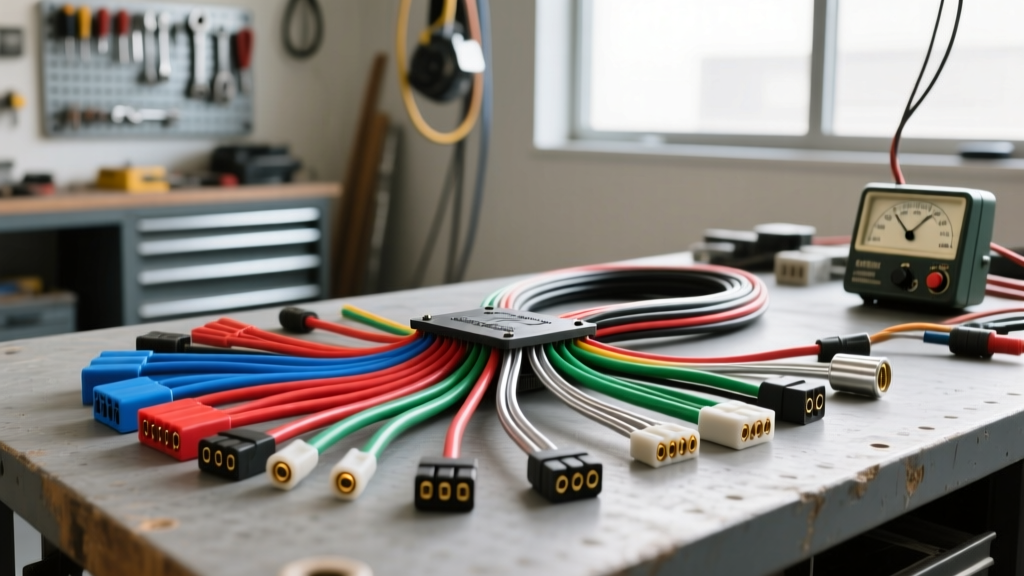
Introduction to AA & T Auto Electric Fundamentals
Entering the world of automotive electrical systems can feel like learning a foreign language. However, the foundational principles of electron flow, circuit resistance, and magnetic induction remain constant across every vehicle on the road. When studying the rigorous diagnostic methodologies championed by top-tier diagnostic shops like AA & T Auto Electric, one core philosophy stands out: never guess, always measure. A beginner-friendly approach to auto electrics does not mean skipping the complex details; it means breaking down those details into actionable, measurable steps.
This guide serves as your foundational blueprint. We will bypass the common 'parts-swapping' mentality and focus on the architecture of vehicle wiring, proper wire gauge selection, connector ecosystems, and the critical diagnostic technique of voltage drop testing. Whether you are restoring a classic muscle car, troubleshooting a daily driver, or integrating aftermarket accessories, understanding these core principles is mandatory for safe and reliable electrical work.
The Core Trinity: Battery, Alternator, and Starter
Every internal combustion vehicle relies on a delicate balance between three primary components: the battery (chemical storage), the alternator (electromagnetic generation), and the starter (electromechanical conversion). Understanding how these components interact is the first step in mastering auto electrical fundamentals.
Starter Circuit Architecture
The starter motor is the highest current-drawing component in a standard 12-volt vehicle, routinely pulling between 150 and 250 amps during cranking. Because of this massive amperage, the starter circuit requires heavy-gauge cabling and pristine connections. Older vehicles utilize a starter solenoid with two primary control terminals:
- S-Terminal (Start): Receives 12V from the ignition switch (often via a neutral safety switch or starter relay) to engage the solenoid plunger.
- R-Terminal (Resistance Bypass): Outputs 12V only during cranking to bypass the ballast resistor, providing full voltage to the ignition coil for a hotter spark during engine start.
Modern vehicles often use gear-reduction starters with integrated solenoids, controlled by the Powertrain Control Module (PCM) via a starter relay to prevent cranking while the engine is already running.
Alternator Pinouts and Sense Circuits
The alternator does not simply 'make power'; it responds to system demand. A classic example is the ubiquitous GM 10SI and CS130 alternator architectures. Understanding the multi-pin connector is crucial for proper charging system operation:
- Terminal L (Lamp/Ignition): Provides the initial 'excitation' current to the alternator's rotor field coil. Without this 12V signal (often routed through the dashboard battery warning lamp), the alternator will not begin generating power.
- Terminal S (Sense): This is the most critical and frequently miswired terminal. The S-terminal monitors actual battery voltage. It must be routed directly to the positive battery post or the main fuse block. If wired directly to the alternator's output post, the alternator will sense its own output voltage, stop charging prematurely, and leave the battery undercharged.
- Terminal I (Ignition): Used in some configurations to provide a secondary switched 12V source to ensure the regulator wakes up when the key is in the 'ON' position.
Wire Sizing and Insulation Standards
Selecting the correct wire gauge is not just about preventing blown fuses; it is about preventing voltage drop and catastrophic electrical fires. In the automotive industry, wire sizing and insulation are governed by the SAE J1128 Standard. Beginners often mistakenly use household THHN wire, which is entirely unsuitable for the vibration, heat, and chemical exposure found under a vehicle's hood.
Understanding Automotive Wire Insulation
Modern auto electricians rely on Cross-Linked Polyethylene (XLPE) insulation rather than standard PVC. You will typically encounter three variants:
- GXL (General Cross-Linked): Standard wall thickness, excellent for general chassis wiring and harness rebuilding.
- SXL (Special Cross-Linked): Thicker insulation, used in high-heat areas or where extra physical abrasion resistance is required.
- TXL (Thin Cross-Linked): Thin-wall insulation. This is the OEM standard for modern vehicles, allowing for smaller, lighter wiring harnesses while maintaining the same current-carrying capacity as thicker GXL wire.
AWG Ampacity Reference Chart
Always size your wire based on the maximum continuous amperage of the circuit and the length of the run. As wire length increases, resistance increases, requiring a thicker gauge to prevent voltage drop. The following table outlines standard AWG (American Wire Gauge) ratings for automotive primary wire (up to 50°C ambient temperature):
| AWG Size | Max Ampacity (Continuous) | Common Automotive Application |
|---|---|---|
| 18 AWG | 6 - 10 Amps | ECM sensors, dashboard lighting, low-draw LEDs |
| 14 AWG | 15 - 20 Amps | Fuel injectors, horn relays, interior accessories |
| 10 AWG | 30 - 40 Amps | Headlight circuits, power windows, radiator fans |
| 8 AWG | 50 - 60 Amps | Alternator output (standard), aftermarket amplifiers |
| 4 AWG | 100 - 120 Amps | High-output alternators, winch power feeds |
| 1/0 AWG | 150 - 200+ Amps | Battery to starter motor main cable |
The Connector Ecosystem: Crimping vs. Soldering
A common beginner mistake is relying on solder and heat shrink for under-hood automotive connections. While solder is excellent for rigid circuit boards, it creates a brittle joint that will inevitably crack under the constant vibration of an internal combustion engine. The AA & T Auto Electric standard—and the standard of every major OEM—is to use mechanically crimped connections with proper environmental seals.
Key Automotive Connector Families
- Delphi (Aptiv) Metri-Pack: The industry standard for OEM engine and chassis sensors. The Metri-Pack 150 series (1.5mm blade width) handles up to 14 amps, while the 280 series (2.8mm blade) handles up to 30 amps. They utilize a secondary lock (TPA - Terminal Position Assurance) to prevent pins from backing out.
- Delphi Weather-Pack: Recognizable by their cylindrical, ribbed bodies and large silicone seals. Rated for up to 20 amps, these are heavily used in older GM vehicles and aftermarket lighting harnesses due to their robust moisture resistance.
- Deutsch DT Series: The gold standard for heavy-duty, off-road, and marine applications. They feature a thermoplastic housing with a silicone rear grommet and utilize solid cylindrical pins that are incredibly resistant to vibration and moisture ingress.
The Art of the Open-Barrel Crimp
Most automotive terminals (like Metri-Pack) use an 'open-barrel' or 'F-crimp' design. To achieve a gas-tight connection, you must use a ratcheting crimp tool specifically designed for open-barrel terminals. The crimp should feature a distinct 'W' or 'M' shape on the wire wings, biting into the copper strands without cutting them, while the insulation wings securely grip the wire jacket. According to Delphi Connection Systems engineering specs, a properly crimped 12 AWG terminal should withstand a minimum pull-force of 50 lbs before the wire yields.
Multimeter Diagnostics: The Voltage Drop Test
If there is one diagnostic skill that separates amateurs from professionals, it is the voltage drop test. Beginners often test for continuity with the circuit powered off, but a wire with only one strand of copper left will show 'continuity' on a multimeter, yet fail completely when asked to carry 20 amps of current under load.
Voltage drop testing measures the exact amount of electrical pressure (voltage) that is being 'lost' as it pushes through a connection or wire while the circuit is actively operating. According to Bosch Mobility Solutions diagnostic guidelines, excessive resistance generates heat, which is the primary cause of melted fuse boxes and failing alternators.
Step-by-Step Voltage Drop Testing
- Set the Multimeter: Turn your digital multimeter (DMM) to DC Volts.
- Energize the Circuit: The circuit MUST be under load. Turn on the headlights, command the cooling fan on, or crank the engine.
- Test the Positive Side: Place the red probe on the positive battery post and the black probe on the component's positive input terminal. Read the voltage.
- Test the Negative Side: Place the red probe on the component's negative terminal and the black probe on the negative battery post. Read the voltage.
Acceptable Voltage Drop Limits
| Circuit Type | Maximum Allowable Drop (Per Connection) | Maximum Total Circuit Drop |
|---|---|---|
| High-Current (Starter/Alternator) | 0.10V | 0.50V total |
| Low-Current (Sensors/ECM) | 0.05V | 0.10V total |
| Lighting / Accessories | 0.10V | 0.20V total |
If your multimeter reads 0.8V across the positive battery cable while cranking, that cable is internally corroded or undersized and must be replaced. By adhering to these strict diagnostic parameters—the very same standards that define the reputation of AA & T Auto Electric and other elite shops—you transform electrical troubleshooting from a frustrating guessing game into a precise, empirical science.
Summary and Next Steps
Mastering auto electrical fundamentals requires patience, the right tools, and a commitment to industry standards. Always reference SAE guidelines for wire sizing, invest in high-quality ratcheting crimpers for OEM-style connectors, and never diagnose a circuit without performing a loaded voltage drop test. By building your knowledge on these core principles, you will be equipped to tackle everything from simple lighting upgrades to complex CAN-bus network diagnostics.