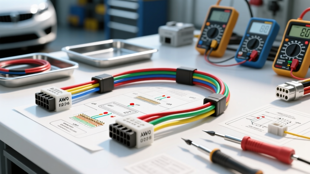
Core Specifications of an Auto Electrical Short Finder
Locating a dead short or parasitic draw in a modern vehicle electrical architecture requires more than a basic digital multimeter (DMM). A dedicated auto electrical short finder—typically utilizing pulsed-tone induction, thermal imaging, or time-domain reflectometry (TDR)—is essential for tracing low-resistance faults through complex wiring harnesses. Unlike a standard continuity test, which only confirms a closed loop, a professional short finder injects a modulated signal or pulsed current into the circuit, allowing the technician to trace the exact physical path of the wire and pinpoint the fault location without stripping back yards of loom tape and corrugated tubing.
Modern vehicles utilize multiplexed networks (CAN, LIN, FlexRay) and high-current feed circuits for components like electric AC compressors and electronic power steering (EPS). Applying the wrong diagnostic signal can destroy sensitive control modules. Therefore, understanding the technical specifications, frequency outputs, and AWG limitations of your short-circuit tracing equipment is critical for safe and accurate diagnostics.
Short Finder Technology Matrix and Signal Specifications
Different fault types require different tracing methodologies. A dead short to ground (0.00 Ω to 2.0 Ω) requires a high-current pulsed signal to generate a detectable magnetic field, while a high-resistance short or cross-circuit fault requires a sensitive tone generator. Below is the technical matrix for common auto electrical short finder technologies.
| Technology Type | Signal Output | Target Fault Resistance | Max AWG Penetration | Primary Use Case |
|---|---|---|---|---|
| Pulsed Inductive (Tone) | 1-2 kHz Square Wave | 0.00 Ω - 5.0 Ω | 10 AWG (Heavy Feed) | Dead shorts to chassis, blown fuses |
| RF Tone Generator | 100-400 kHz RF Sweep | 5.0 Ω - 100 Ω | 18 AWG (Sensor/Signal) | Crossed wires, high-resistance grounds |
| Thermal Tracing | DC Current Injection (1-10A) | 0.00 Ω - 0.5 Ω | 4 AWG (Starter/Alt) | Parasitic draws, hidden harness chafing |
| Time-Domain Reflectometry | High-Frequency Voltage Pulse | Open / Short / Impedance Mismatch | CAN-Bus / Coax | Network topology faults, broken shields |
AWG Wire Gauge and Resistance Thresholds
When using an auto electrical short finder, the American Wire Gauge (AWG) size dictates the resistance per foot, which directly impacts signal attenuation and voltage drop. According to the SAE J1128 Low Tension Primary Cable Standard, automotive primary wire (GXL, TXL, SXL) features cross-linked polyethylene insulation designed for high-temperature resistance, but the copper stranding resistance remains consistent with standard electrical physics.
If you are injecting a 5-amp pulsed signal to trace a short on a fuel pump circuit, the voltage drop across the wire will determine how far the signal can travel before the short finder's inductive wand loses detection. Refer to the specification chart below for standard automotive GXL wire resistance thresholds.
| AWG Size | Stranding (Nominal) | Ohms per 1,000 ft (Copper @ 20°C) | Max Tracing Distance (5A Pulse) | Common Application |
|---|---|---|---|---|
| 18 AWG | 16/30 | 6.385 Ω | ~15 ft | Injectors, Sensors, CAN-Bus |
| 16 AWG | 26/30 | 4.016 Ω | ~25 ft | Lighting, Horn, Radio Memory |
| 14 AWG | 41/30 | 2.525 Ω | ~40 ft | Fuel Pump Feed, Power Windows |
| 12 AWG | 65/30 | 1.588 Ω | ~65 ft | AC Compressor Clutch, ABS Valves |
| 10 AWG | 104/30 | 0.998 Ω | ~100 ft | EPS Feed, Starter Solenoid, Main Power |
Probing Methodologies for Common Automotive Connectors
A critical failure point in short-circuit diagnostics is improper probing, which can compromise the environmental seals of a connector or spread the terminal pins. When connecting your auto electrical short finder to a circuit, you must interface with the correct pinout without damaging the terminal.
Deutsch DT and DTM Series Connectors
Commonly used in heavy-duty, off-road, and under-hood applications, the Deutsch DT series utilizes Size 16 stamped and formed contacts rated for 13 amps, accommodating 14-18 AWG wire. The DTM series uses Size 20 contacts for 18-22 AWG signal wires.
- Pin Extraction: Never probe the front mating face of a Deutsch connector. Use a Deutsch DT extractor tool to push the orange or green wedge lock inward, pull the pin out from the rear, and connect the short finder's alligator clip directly to the crimp barrel.
- Sealing Integrity: The rear grommet provides IP67 sealing. Piercing the wire insulation behind the grommet with a test probe defeats this seal, allowing moisture to enter via capillary action, leading to green copper oxide corrosion (verdigris) inside the crimp barrel within 6 to 12 months.
Metri-Pack and Weather-Pack Systems
As detailed in the Aptiv Connection Systems Catalog, Weather-Pack connectors utilize cylindrical pins with specific tangs for locking. The 150 series handles 14-18 AWG, while the 280 series handles 10-12 AWG. When injecting a tone signal into a Weather-Pack tower (male) or shroud (female), utilize dedicated back-probes that slide past the silicone ribbed seals. Never use standard sewing pins or paperclips, as they will permanently deform the beryllium copper contact spring, resulting in a high-resistance connection or intermittent open circuit.
Step-by-Step Tracing Protocol: 30A AC Compressor Clutch Circuit
Consider a scenario where a late-model SUV presents with a blown 30A maxi-fuse for the electric AC compressor clutch. The circuit utilizes a 12 AWG Red/White stripe wire routed from the under-hood fuse block, through the firewall grommet, to the compressor connector.
- Circuit Isolation: Remove the blown 30A fuse. Disconnect the compressor clutch connector to isolate the load. Verify the short is in the harness, not the clutch coil, by measuring resistance across the clutch pins (should be 3.5 - 4.5 Ω). A reading of 0.0 Ω on the harness side confirms a dead short to chassis ground.
- Signal Injection: Connect the red lead of the pulsed auto electrical short finder to the load-side terminal of the fuse box slot. Connect the black lead to a known clean chassis ground (verify < 0.05V drop under load).
- Wand Calibration: Power on the inductive tracing wand. Adjust the sensitivity dial until the LED indicator or audio tone registers a strong pulse near the fuse box, then back off the sensitivity slightly to narrow the detection field.
- Path Tracing: Follow the harness routing. The wand will emit a rhythmic clicking or tone as long as the pulsed current is flowing. When the wand passes the exact point where the 12 AWG wire is chafed against the aluminum radiator support bracket, the magnetic field will collapse, and the tone will abruptly stop.
- Fault Verification: Visually inspect the silent zone. You will typically find the GXL insulation worn through to the copper stranding. Repair using a solder-sleeve splice or cut-and-crimp method with adhesive-lined heat shrink to restore the IP67 environmental seal.
Environmental and Mechanical Failure Modes
When tracing shorts, understanding why the short occurred prevents repeat failures. Common failure modes include:
- Fretting Corrosion: In 2.8mm female blade connectors, micro-vibrations from the engine bay cause the terminal to wear against the male tab. This creates metallic dust that, combined with humidity, creates a conductive path between adjacent pins (cross-circuit short).
- Thermal Insulation Breakdown: Routing 14 AWG primary wire too close to the exhaust manifold or turbocharger downpipe can exceed the 125°C rating of GXL wire. The insulation becomes brittle and flakes off, causing a short to the heat shield.
- Pin Migration: If the terminal crimp was performed without the proper ratcheting tool, the wire insulation may not be fully seated against the terminal shoulder. Over time, thermal cycling causes the wire to push the pin backward out of the connector cavity, shorting against the adjacent metal retaining clip or connector shell.
For advanced circuit testing and pulsed-load diagnostics, technicians frequently rely on Power Probe Circuit Testing Documentation to safely inject current and monitor voltage drops in real-time, ensuring the auto electrical short finder is used within the safe thermal limits of the vehicle's wiring architecture.