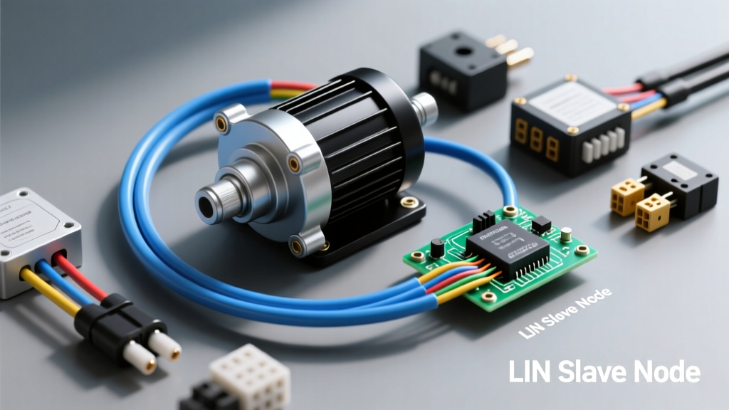
Automotive Electric Coolant Pump Architectures
The transition from mechanical, belt-driven water pumps to brushless DC (BLDC) auto electric water pump systems represents a fundamental shift in modern vehicle thermal management. Unlike mechanical pumps that tie coolant flow directly to engine RPM, electric coolant pumps allow the Engine Control Module (ECM) or Thermal Management Module (TMM) to precisely regulate flow based on real-time thermal loads. From an electrical standpoint, these pumps are not simple 12V DC motors; they are sophisticated 3-phase BLDC motors with integrated internal inverter bridges and microcontroller logic.
Understanding the wiring architecture, Pulse Width Modulation (PWM) or Local Interconnect Network (LIN) control signals, and power delivery requirements is critical for accurate diagnostics and aftermarket installations. According to SAE J1455 environmental standards for heavy-duty and automotive electronic equipment, underhood components like electric water pumps must withstand extreme thermal cycling, voltage transients (load dump), and high-frequency electromagnetic interference (EMI) from adjacent ignition systems.
Primary vs. Auxiliary Pump Electrical Loads
Auto electric water pumps are generally categorized into two distinct electrical load profiles:
- Primary Electric Coolant Pumps: Found in EVs, hybrids, and modern turbocharged ICE vehicles (e.g., Ford EcoBoost, BMW B58). These pumps move high volumes of coolant and draw significant current, typically ranging from 15A to 40A under peak load (400W–800W). They require heavy-gauge power feed circuits and dedicated high-amperage relays or solid-state power distribution modules.
- Auxiliary Electric Coolant Pumps: Used for localized cooling, such as turbocharger bearing housing cooling after engine shutoff, intercooler circuits, or heater core circulation. These are typically 15W to 50W devices, drawing 1A to 4A, and are often fed via standard 10A or 15A fused circuits.
PWM Control Signal Specifications & Pinouts
The ECM communicates with the auto electric water pump using either a raw PWM signal or a LIN bus protocol. Raw PWM is common in older and simpler auxiliary circuits, while LIN bus is standard for modern primary pumps requiring bidirectional feedback (e.g., reporting internal temperature, rotor speed, and fault codes back to the ECM).
Below is the standard 4-pin BLDC pump connector pinout commonly utilized in European and late-model domestic applications (e.g., TE Connectivity Superseal 1.5 or Sumitomo 0.64 series connectors).
| Pin | Function | Wire Color (Typical) | AWG | Specification / Voltage |
|---|---|---|---|---|
| 1 | KL30 (Battery Power) | Red or Red/White | 10 AWG - 14 AWG | Constant 12V-14.5V DC (Fused) |
| 2 | KL31 (Chassis Ground) | Brown or Black/White | 10 AWG - 14 AWG | Clean chassis ground (< 0.05Ω) |
| 3 | PWM / LIN Signal | Yellow/Red or Violet/Orange | 20 AWG - 22 AWG | 100Hz-500Hz PWM (0-12V) or LIN 19.2 kbps |
| 4 | Feedback / Tach (Optional) | Blue or Green/White | 22 AWG | 0-5V Square Wave (Pulse per revolution) |
PWM Duty Cycle Mapping & Fail-Safe Modes
The ECM dictates pump speed by varying the duty cycle of the PWM signal. However, the mapping is rarely linear, and understanding the fail-safe states is crucial for diagnosing severed wires or ECM faults.
- 10% Duty Cycle: Pump initialization / Standby (Motor off, internal logic powered).
- 15% - 85% Duty Cycle: Active speed control mapping (Linear or mapped curve based on coolant temp).
- 90% Duty Cycle: Maximum commanded speed (Emergency over-temperature mode).
- 95% - 99% Duty Cycle: Electrical bleeding / Air purge routine (Cycles between 40% and 90% to bleed air from the heater core).
- Open Circuit (Wire Severed): Most European auto electric water pumps feature an internal pull-up resistor. If the PWM wire breaks, the pump defaults to 100% ON to prevent catastrophic engine overheating. Conversely, many Asian domestic market (ADM) pumps default to 0% OFF via a pull-down resistor to prevent electrical fires in short-circuit scenarios.
Relay-Based Auxiliary Pump Wiring Diagrams & AWG Sizing
When retrofitting an auto electric water pump for aftermarket turbo cooling or custom intercooler setups, proper wire gauge selection is mandatory to prevent voltage drop and thermal degradation. According to Bosch Motorsport Technical Guidelines, wire sizing must account for total circuit length (power + ground) and continuous amperage draw.
| Max Continuous Draw | Wire Length (Under 10 ft) | Wire Length (10-20 ft) | Recommended Fuse |
|---|---|---|---|
| 5A (Auxiliary Pump) | 18 AWG | 16 AWG | 7.5A Mini |
| 15A (Small Primary) | 14 AWG | 12 AWG | 20A ATO |
| 30A (Large Primary) | 10 AWG | 8 AWG | 40A MIDI/AME |
| 50A (High-Flow EV) | 8 AWG | 6 AWG | 60A MEGA |
Routing Note: The 20 AWG PWM signal wire must never be routed parallel to ignition coil primary wires or fuel injector circuits. High-frequency EMI from inductive spikes can induce phantom voltage in the PWM line, causing the water pump microcontroller to misinterpret the signal, resulting in erratic surging or sudden pump shutoff.
Diagnostic Troubleshooting & Oscilloscope Waveforms
Diagnosing a failing auto electric water pump requires moving beyond simple multimeter voltage checks. Because the internal MOSFET bridge draws current in high-frequency pulses, a standard digital multimeter (DMM) will often display erratic or averaged voltage readings that are useless for diagnostics. An automotive oscilloscope is mandatory.
Symptom-Cause-Fix Decision Tree
- Symptom: Pump runs at 100% constantly, ignoring engine temperature.
Cause: Open circuit on the PWM signal wire, or ECM driver failure.
Fix: Backprobe Pin 3 at the pump connector with ignition ON, engine OFF. If 12V is present but no PWM wave is visible on the scope, trace the wire back to the ECM for a break. If the wire has continuity, suspect an internal ECM driver fault. - Symptom: Pump is completely dead; no current draw on inductive amp clamp.
Cause: Internal thermal fuse blown, or catastrophic MOSFET bridge failure due to coolant ingress.
Fix: Verify clean power and ground at Pins 1 and 2 under load. If power is present but the pump draws 0A, the internal electronics have failed. Replacement of the pump assembly is required; these units are sealed and non-serviceable. - Symptom: Intermittent pump stalling at high RPM.
Cause: EMI interference on the LIN/PWM bus, or excessive voltage ripple from a failing alternator diode trio.
Fix: Scope the AC ripple on the battery terminals (should be < 100mV AC). If ripple is high, replace the alternator. If ripple is normal, inspect the PWM wire shield (if equipped) or reroute the signal wire away from the ignition coil harness. - Symptom: ECM throws 'Water Pump Speed Deviation' code (e.g., BMW 20A802).
Cause: Mechanical binding, air lock, or degraded internal bearings causing the actual RPM to deviate from the ECM's target map.
Fix: Perform a software-controlled coolant bleed procedure to eliminate air pockets. If the code persists and the coolant system is fully bled, the internal hall-effect sensor or bearing assembly has degraded. Replace the pump.
Connector Types & Terminal Torque Specifications
When repairing wiring harnesses leading to the auto electric water pump, proper terminal crimping and sealing are non-negotiable. The underhood environment exposes connections to water spray, road salt, and extreme heat radiating from the exhaust manifold or turbocharger.
- Connectors: Most modern pumps use TE Automotive Superseal 1.5, Molex MX150, or Sumitomi 0.64 unsealed (if located inside the cabin/heater box) connectors. Always use the correct extraction tool to avoid damaging the plastic retention tangs.
- Crimping: Use a ratcheting crimp tool specific to the terminal series. Soldering is strictly prohibited on automotive crimp terminals in high-vibration zones, as solder wicking creates a rigid stress point that will eventually fracture the copper strands.
- Weatherpack Seals: Ensure the silicone wire seals are inserted before crimping the terminal. A missing or pinched seal will allow capillary action to draw moisture directly into the pump's internal microcontroller, leading to corrosion and short-circuit failures.
- Banjo Bolt / Ground Ring Torque: If the pump grounds via a mounting bolt or a dedicated ground ring terminal to the engine block, the mating surface must be sanded to bare metal. Torque the ground bolt to the manufacturer's specification (typically 8-12 Nm for M6 bolts) to ensure a low-resistance path. A poor ground will cause the internal logic board to reset randomly under high-load 3-phase commutation.