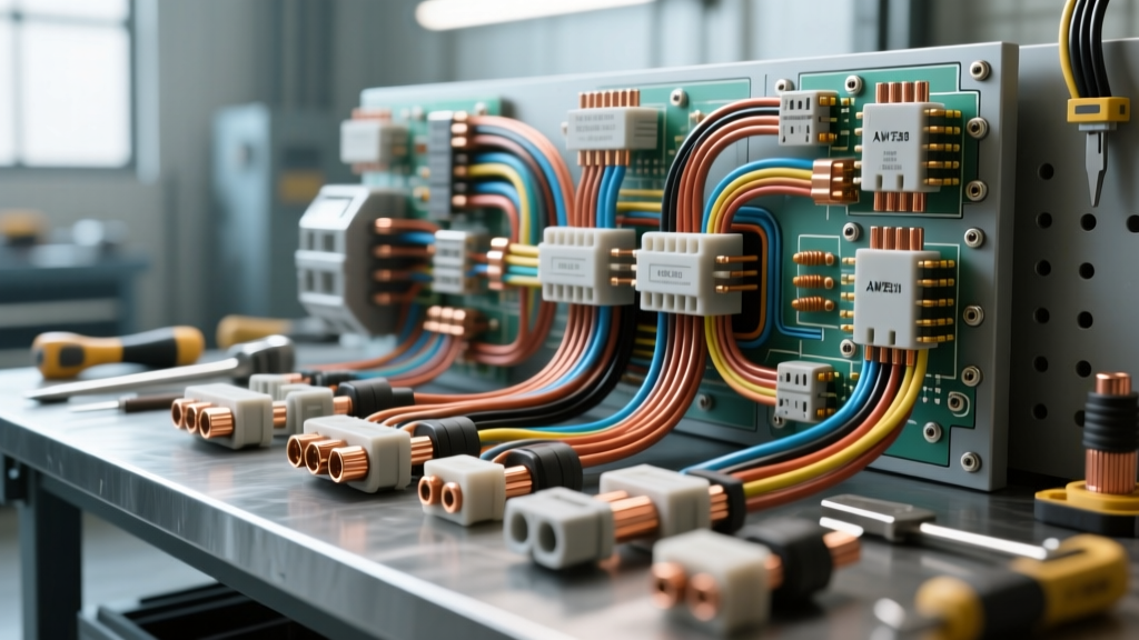
Auto Electrical Basics: The High Cost of Wiring Mistakes
Understanding auto electrical basics is the difference between a reliable vehicle and a rolling fire hazard. While many DIY enthusiasts and junior technicians focus on making a component turn on, true electrical mastery lies in safely containing electron flow, managing heat dissipation, and protecting sensitive control modules. A single misplaced ground or over-fused circuit can melt a wiring harness or destroy a $2,000 Engine Control Unit (ECU).
This guide dives deep into the most dangerous and common mistakes made in automotive wiring. By referencing SAE J1128 standards for low-tension cable and industry-standard relay pinouts, we will outline the exact failure modes and safety protocols required for professional-grade electrical work.
Mistake 1: The 'Ground Anywhere' Fallacy
The most pervasive error in auto electrical basics is assuming that any bare metal on the chassis or engine block is a viable ground. Modern vehicles utilize extensive rust-prevention treatments, including e-coating, powder coating, and seam sealants. These materials are highly resistive and will create a voltage drop across your ground circuit.
The ECU Ground Failure Mode
When an ECU (such as a Bosch Motronic or Honda PGM-FI system) attempts to ground a fuel injector driver through a high-resistance chassis point, the current seeks the path of least resistance. This often routes the return current backward through the ECU's internal 5V reference logic board, instantly frying the microprocessor.
Correct Grounding Protocol
- Surface Prep: Strip all paint, powder coat, and rust down to bare, shiny metal using a wire wheel or 80-grit sandpaper.
- Hardware: Always use an internal-tooth star washer between the ring terminal and the chassis. The teeth must bite directly into the bare metal, not the paint.
- Terminal Sizing: For a 10 AWG ground wire, use a #10 ring terminal sized for a 5/16" or M8 stud. Do not crimp a 1/4" terminal and force it over a 5/16" bolt, which deforms the barrel and increases resistance.
- Torque Spec: Tighten M8 ground bolts to 12-15 ft-lbs. Under-torquing allows vibration loosening; over-torquing strips the threads and reduces clamping force.
- Corrosion Protection: After tightening, coat the entire terminal and exposed bare metal with a dielectric grease or zinc-rich cold galvanizing compound to prevent galvanic corrosion.
Mistake 2: Overfusing and the 'Upsizing' Trap
A fundamental rule of auto electrical basics is that a fuse protects the wire, not the component. When a circuit repeatedly blows a fuse, the amateur response is to install a higher-amperage fuse. This is a critical safety violation that turns your wiring harness into a heating element.
According to Haynes automotive electrical tutorials, wire gauge (AWG) dictates the maximum safe current capacity. Exceeding this capacity causes the copper to heat up, melting the PVC or cross-linked polyethylene (XLPE) insulation and shorting against the chassis.
AWG to Fuse Rating Specification Chart
| Wire Gauge (AWG) | Cross-Section (mm²) | Max Continuous Ampacity | Max Safe Fuse Size | Common Application |
|---|---|---|---|---|
| 18 AWG | 0.80 mm² | 7 Amps | 5A or 7A | ECU sensors, dashboard LEDs |
| 16 AWG | 1.30 mm² | 10 Amps | 10A | Interior lighting, horn relay coil |
| 14 AWG | 2.00 mm² | 15 Amps | 15A | Fuel pump (low draw), headlights |
| 12 AWG | 3.30 mm² | 20 Amps | 20A | Power windows, cigarette lighter |
| 10 AWG | 5.20 mm² | 30 Amps | 30A | EFI fuel pumps, radiator fans |
| 8 AWG | 8.30 mm² | 45 Amps | 40A or 50A | Alternator output, starter solenoid |
Warning: If a 15A circuit on 14 AWG wire keeps blowing, you have a dead short or a failing component. Never replace it with a 20A fuse.
Mistake 3: Destroying ECUs with Inductive Kickback
When wiring high-draw components like cooling fans or fuel pumps, a relay is mandatory. However, improperly wiring the relay coil trigger can destroy the ECU's internal driver transistor. Standard ISO mini relays utilize pins 85 and 86 for the electromagnetic coil. When the ECU cuts power to the coil (breaking the ground on Pin 85), the collapsing magnetic field generates a massive reverse voltage spike (inductive kickback) that can exceed 100 volts.
The Flyback Diode Solution
To protect sensitive ECU drivers (such as the Honda PGM-FI ECU Pin A8 fan trigger), you must install a flyback diode across the relay coil.
- Use a standard 1N4001 or 1N4004 rectifier diode.
- Solder the diode directly across relay pins 85 and 86.
- Critical Orientation: The silver stripe on the diode (cathode) MUST face the 12V+ source (Pin 86). The non-striped end (anode) faces the ECU ground trigger (Pin 85).
- This allows the reverse voltage spike to loop safely back through the coil, dissipating harmlessly instead of traveling back into the ECU.
Mistake 4: Alternator Sense Wire Misrouting
Upgrading to a high-output alternator (e.g., 200A+) requires understanding the 'S' (Sense) terminal. A common mistake is looping the sense wire directly to the alternator's main output post (B+). This tells the alternator's internal regulator that the battery is fully charged, causing it to drop output voltage to 12.8V, resulting in a perpetually undercharged battery.
Correct Sense Wire Routing
The sense wire must read the actual voltage at the battery or the main distribution block. Run a 14 AWG red wire from the alternator 'S' terminal directly to the positive battery terminal or the main starter junction block. Safety Warning: Because this wire is tied directly to the battery, it is 'hot' at all times. You MUST install an inline 10A MAXI fuse within 6 inches of the battery connection point to prevent a harness fire in the event the wire chafes against the exhaust or block.
Pre-Power Safety Decision Tree
Before reconnecting the battery and applying power to a newly wired circuit, run through this mandatory safety checklist to prevent catastrophic shorts:
- Step 1: The Tug Test. Physically pull on every crimped connection. A proper ratcheting crimp (meeting Delphi/Packard specifications) will withstand over 40 lbs of pull force without the wire slipping from the barrel.
- Step 2: Multimeter Continuity Check. With the battery disconnected, set your multimeter to continuity. Place one probe on the circuit's main power feed and the other on a known good chassis ground. The meter should read 'OL' (Open Loop). If it beeps, you have a dead short to ground. Do not apply power.
- Step 3: Fuse Verification. Visually verify that the installed fuse matches the AWG wire size chart above. Never rely on memory.
- Step 4: The Bulb Test (Optional but Recommended). For complex custom harnesses, wire a standard 1156 incandescent bulb in series with the main battery feed. If a dead short exists, the bulb will light up brightly, limiting current and preventing harness damage while you troubleshoot.
Conclusion
True proficiency in auto electrical basics requires a paranoid respect for current flow and heat. By adhering to SAE wiring standards, utilizing proper grounding hardware, sizing fuses to protect the copper, and shielding ECUs from inductive spikes, you ensure that your vehicle's electrical system remains safe, reliable, and fire-free. For further reading on OEM connector pinouts and wire color codes, consult your vehicle's specific factory service manual or trusted resources like Bosch Mobility Solutions.