The Domain of Auto Electric Specialties
When enthusiasts and technicians transition from basic 12-volt accessory installations to the realm of auto electric specialties, the margin for error shrinks dramatically. Specialty automotive electrical work encompasses high-amperage inverter circuits, Controller Area Network (CAN-bus) multiplexing, electric vehicle (EV) high-voltage interlocks, and heavy-duty solenoid arrays. Unlike running a simple 18 AWG wire to a low-draw LED light bar, specialty circuits demand a rigorous understanding of thermal dynamics, electromagnetic interference (EMI), and precise network topology.
Treating specialty circuits with standard DIY wiring logic is a primary cause of electrical fires, module bricking, and catastrophic voltage drops. This guide dissects the most dangerous mistakes made in specialized automotive wiring and provides the exact technical corrections required to maintain system integrity and operator safety.
Mistake 1: Undersizing High-Current Specialty Circuits
The most pervasive error in auto electric specialties is relying on standard American Wire Gauge (AWG) charts meant for residential or static 12V applications without accounting for the harsh under-hood environment and voltage drop over distance.
The Physics of Voltage Drop and Insulation Melt
Standard PVC-insulated wire is entirely unsuitable for high-amperage specialty circuits routed near exhaust manifolds or engine blocks. PVC insulation begins to soften and degrade at temperatures exceeding 105°C (221°F). When routing power for an electric AC compressor, a high-output alternator upgrade, or a winch solenoid, you must use Cross-Linked Polyethylene (XLPE) or silicone-insulated wire, which can withstand continuous temperatures up to 150°C (302°F). This requirement is strictly outlined in the SAE J1128 Standard for Low Tension Primary Cable.
Furthermore, wire sizing must be calculated based on voltage drop, not just ampacity. A 40-amp electric fan drawing power through 20 feet of 10 AWG wire will suffer a voltage drop of approximately 0.8V, which is acceptable. However, if that same 10 AWG wire is used for a 60-amp specialty fuel pump located 25 feet away, the voltage drop exceeds 1.5V. The pump will run hotter, draw even more current to compensate for the lower voltage, and ultimately melt the wire insulation, causing a dead short to the chassis.
- 30A Specialty Circuit (e.g., E-Fan Relay): Minimum 10 AWG XLPE wire, protected by a 40A MAXI fuse.
- 60A Specialty Circuit (e.g., Inverter Feed): Minimum 6 AWG wire, protected by a Class T fuse.
- 150A+ Circuit (e.g., Winch/Starter): Minimum 2/0 AWG welding cable, utilizing an ANL or Class T fuse within 18 inches of the battery positive terminal.
Mistake 2: Splicing into CAN-Bus Multiplex Networks
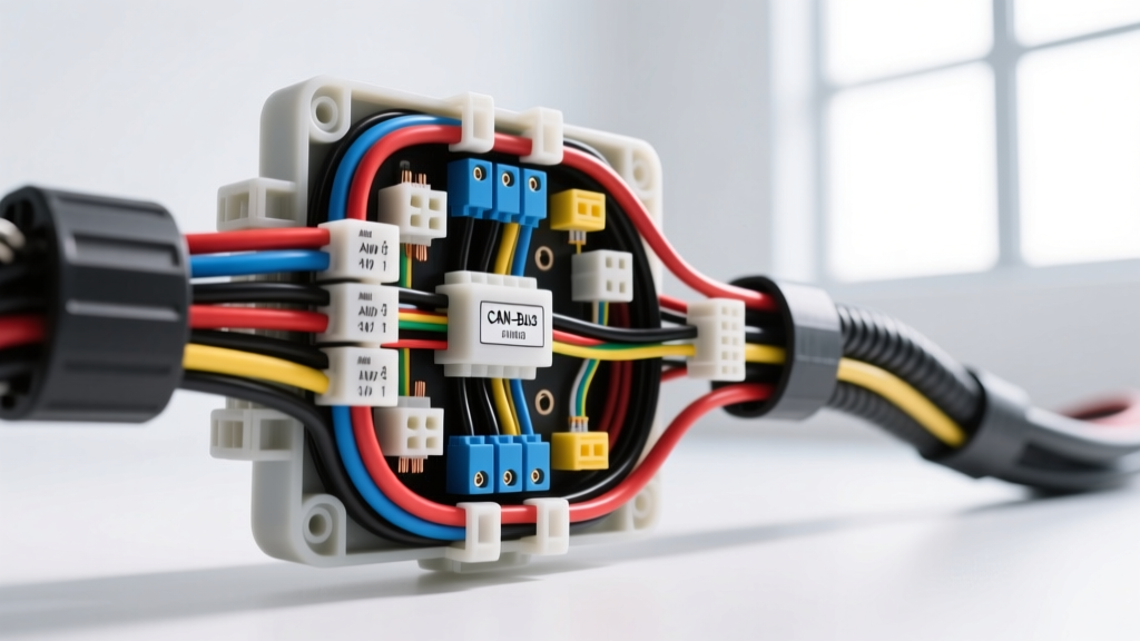
Modern auto electric specialties heavily involve network diagnostics and module integration. A fatal mistake occurs when installers attempt to 'tap' into CAN-High and CAN-Low wires to trigger aftermarket alarms, telemetry modules, or remote starts using standard solder-and-tape splices.
OBD-II Pinouts and Termination Resistors
CAN-bus networks utilize differential signaling to reject EMI. The network relies on a twisted pair of wires (typically twisted 3 to 4 times per inch). Splicing into these wires using scotch-locks or untwisting them for more than a few millimeters alters the characteristic impedance of the cable, causing signal reflection and network-wide communication failures.
At the OBD-II diagnostic port, CAN-High is located at Pin 6 and CAN-Low is at Pin 14. In a dormant (recessive) state, both lines sit at approximately 2.5V. During active (dominant) communication, CAN-High spikes to ~3.5V while CAN-Low drops to ~1.5V. If an installer accidentally bridges these lines, or if a poorly installed aftermarket module lacks proper optical isolation, the entire powertrain control module (PCM) network will crash, resulting in a no-start condition and a dashboard lit up like a Christmas tree.
Additionally, high-speed CAN networks require 120-ohm termination resistors at each physical end of the bus. If you are building a custom specialty harness for a race car or engine swap, failing to install these resistors will result in erratic voltage oscillations. Always verify network health by measuring resistance between Pin 6 and Pin 14 with the battery disconnected; a healthy dual-terminated network will read exactly 60 ohms (two 120-ohm resistors in parallel). For deeper network protocols, refer to the SAE J1939 Network Standard.
Mistake 3: Daisy-Chaining High-Draw Grounds
Grounding is the return path of the circuit, yet it is frequently treated as an afterthought. In auto electric specialties, daisy-chaining grounds (connecting multiple high-draw component ground wires to a single ring terminal) creates a bottleneck. If a 40A electric water pump and a 20A fuel pump share a single 10 AWG ground wire and a single M8 chassis bolt, the return current (60A) will exceed the wire's capacity, causing the ground wire to overheat and potentially melt against the chassis.
Star Grounding and Torque Specifications
Specialty electrical architecture requires a Star Point Grounding topology. Each high-draw component must have its own dedicated ground wire routed to a centralized, heavy-duty ground busbar or a dedicated, unpainted chassis stud.
When securing ground ring terminals to the chassis, paint, powder coating, and rust act as insulators. You must use a wire brush or sanding disc to expose bare, shiny metal. To prevent galvanic corrosion and ensure low contact resistance, apply a thin layer of dielectric grease or specialized conductive anti-seize over the bare metal after tightening. Torque specifications are critical: an M8 (8mm) ground bolt should be torqued to approximately 22 Nm (16 lb-ft), while an M10 (10mm) battery terminal or engine block ground stud requires 35 Nm (26 lb-ft) to prevent vibration-induced loosening and subsequent arcing.
Safety Warning & Correction Matrix
The following matrix outlines common hazards encountered in specialty auto electrical work and their engineered solutions.
| Hazard Scenario | Component / System | Common Mistake | Corrective Action |
|---|---|---|---|
| Thermal Runaway / Fire | High-Amp Inverter Feed | Using standard ATC blade fuses for 80A+ circuits. | Install a Class T fuse with high interrupting capacity within 18 inches of the battery. |
| Module Bricking / Network Crash | CAN-Bus Telemetry | Splicing into CAN-H/CAN-L with twist-on wire connectors. | Use a dedicated CAN-bus breakout module or solder with adhesive-lined heat shrink, maintaining the twisted pair. |
| Arcing / Voltage Drop | Starter Solenoid / Winch | Reusing stretched or oxidized copper lug terminals. | Use heavy-duty, closed-barrel copper lugs crimped with a hydraulic crimper and sealed with marine-grade heat shrink. |
| EMI Interference | Ignition Coils / Sensors | Routing 5V sensor signal wires parallel to 12V ignition wires. | Rout signal wires at a 90-degree angle to high-voltage/ignition wires and utilize shielded twisted pair (STP) cable. |
Mistake 4: Using Solder-Only or Twist-On Connections
In the vibration-heavy environment of an automobile, solder-only connections are a severe safety hazard. Solder is rigid; when subjected to engine harmonics and chassis flex, the solder joint will work-harden, crack, and eventually fail, creating a high-resistance connection that generates intense localized heat.
The Superiority of Adhesive-Lined Heat Shrink and Crimps
The IPC/WHMA-A-620 Wiring Standards dictate that automotive wire terminations must rely on mechanical crimping for electrical and physical connectivity. For auto electric specialties, open-barrel crimps (used in OEM harnesses) are excellent, but for aftermarket heavy-duty applications, closed-barrel crimps with adhesive-lined heat shrink are mandatory.
When terminating specialty sensors or high-vibration components, utilize environmental connectors such as the Deutsch DT series (rated for 13 amps per size 16 pin) or the Deutsch DTP series (rated for 25 amps per size 12 pin). These connectors feature silicone rear wire seals and internal O-rings that make them entirely waterproof and resistant to automotive fluids. Never use standard 'bullet' connectors or exposed spade terminals in under-hood specialty applications, as moisture ingress will rapidly cause copper oxidation and signal degradation.
Conclusion: Respect the Architecture
Mastering auto electric specialties requires shifting your mindset from simply 'making a connection' to engineering a reliable, fault-tolerant pathway for electrons. By respecting AWG voltage drop limitations, preserving CAN-bus network topology, implementing star-grounding strategies, and utilizing proper environmental crimp connectors, you ensure that high-performance electrical systems operate safely and reliably under the most extreme automotive conditions.