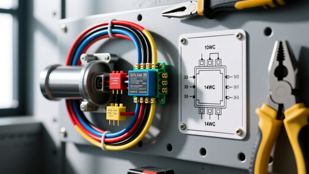
Why Upgrade to an Auto Electric Oil Pump?
When performing high-performance engine builds, turbocharger installations, or dry-sump conversions, protecting your engine bearings and turbo cartridges during startup and shutdown is critical. Installing an auto electric oil pump as a dedicated pre-lube and post-shutdown cooling system is one of the most effective modifications you can make. Unlike mechanical pumps that rely on engine RPM, an auto electric oil pump operates on a 12V DC circuit, allowing it to build vital oil pressure before the starter motor even engages the flywheel, and continue circulating oil after the ignition is turned off to prevent turbo bearing coking.
However, integrating a high-current 12V DC pump into a modern vehicle electrical architecture requires precise relay logic, proper wire gauge selection, and robust grounding. A poorly wired auto electric oil pump can cause severe voltage drop, alternator overload at idle, or catastrophic failure of the turbocharger due to relay chatter. This guide details the exact electrical specifications, wiring schematics, and relay logic required to safely integrate an aftermarket 12V oil pump into your vehicle.
Electrical Load and Alternator Sizing Considerations
Before cutting a single wire, you must evaluate your vehicle's charging system. Most high-flow 12V auto electric oil pumps (such as the Pierburg CWA or high-end Shurflo bypass models) draw between 10 to 18 amps under load, with a startup inrush current that can briefly spike to 25 amps. If your vehicle is equipped with a stock 80-amp alternator and you are already running electric cooling fans, a high-output fuel pump, and an MSD ignition box, adding a continuous 15-amp draw at idle may push the alternator past its thermal limits.
For dedicated turbo pre-lube applications, the pump typically runs for 15 to 30 seconds during pre-start, and 60 seconds post-shutdown (when the alternator is no longer spinning). Therefore, the load is primarily handled by the battery. However, if your logic dictates that the auto electric oil pump runs continuously as a scavenge pump while the engine is operating, upgrading to a high-output alternator (140A to 200A) and utilizing 4 AWG alternator charge wire is highly recommended to prevent system voltage from dropping below 13.2V.
Component Bill of Materials and Specifications
To ensure reliability in the harsh under-hood environment, all components must meet automotive-grade thermal and vibration standards. Below is the required hardware list for a robust auto electric oil pump installation.
| Component | Specification | Purpose |
|---|---|---|
| Primary Power Wire | 10 AWG Tefzel (MIL-W-22759/16) | Main power feed from battery to relay; high temp resistance. |
| Control Circuit Wire | 14 AWG TXL (SAE J1128) | Low-current trigger wires for relays and Hobbs switch. |
| Main Power Relay | Bosch-style 40A SPDT (5-Pin) | Handles the high amperage inrush of the pump motor. |
| Oil Pressure Switch | Hobbs Switch (Normally Closed, 5 PSI) | Breaks the ground circuit once mechanical oil pressure is achieved. |
| Inline Fuse | 20A ATO/ATC Blade Fuse | Protects the 10 AWG main power circuit from dead shorts. |
| Connectors | Deutsch DT 2-Pin & Weather-Pack | Sealed, vibration-proof connections for the pump and sensors. |
The Control Logic: Hobbs Switch and Relay Integration
The most common mistake enthusiasts make when wiring an auto electric oil pump is using a simple toggle switch or wiring it directly to an ignition-switched 12V source without oil pressure feedback. If the pump runs while the mechanical oil pump is already generating 60 PSI, you risk blowing out the oil filter seals or over-pressurizing the turbo feed lines. The correct method utilizes a Normally Closed (NC) Hobbs oil pressure switch paired with an ignition-switched trigger.
Step 1: Main Power and Ground Distribution
Begin by routing a 10 AWG Tefzel wire from the positive battery terminal. Install a 20A ATO inline fuse holder within 6 inches of the battery post. Route this wire to the engine bay, keeping it away from exhaust manifolds and moving accessories. Terminate this wire at Pin 30 of your 40A Bosch-style relay.
For the pump ground, do not rely on engine block casting grounds, which can suffer from paint, corrosion, and galvanic interference. Weld a dedicated M8 ground stud to the chassis near the pump mounting location. Sand the mating surface down to bare metal, treat it with Noalox anti-oxidant compound, and secure a heavy-duty brass ring terminal with a star washer and brass nut. Connect the pump's negative lead directly to this dedicated chassis ground using a sealed Deutsch DT connector.
Step 2: Wiring the Hobbs Oil Pressure Switch
The Hobbs switch is the brain of the pre-lube operation. Install the NC Hobbs switch into a dedicated oil gallery port (preferably near the oil filter housing or turbo feed block). Because the switch is Normally Closed, it will allow continuity when oil pressure is below 5 PSI, and break the circuit once pressure exceeds 5 PSI.
Run a 14 AWG TXL wire from Pin 86 of the main relay to one terminal of the Hobbs switch. Run a second 14 AWG wire from the other Hobbs switch terminal to a verified, clean chassis ground. This means Pin 86 will only see a ground path when the engine has zero oil pressure.
Step 3: Ignition-Switched Trigger Circuit
To prevent the auto electric oil pump from running continuously and draining the battery when the car is parked, Pin 85 of the relay must be tied to an ignition-switched 12V source. Locate a fuse in the interior fuse box labeled 'IGN' or 'ECU' that only receives power in the 'ON' and 'START' positions. Use an Add-A-Circuit fuse tap with a 5A mini-blade fuse to safely draw this trigger signal. Route this 14 AWG wire through the firewall and connect it to Pin 85 of the relay.
Finally, connect Pin 87 of the relay to the positive terminal of the auto electric oil pump. When you turn the key to the 'ON' position, Pin 85 receives 12V. Because the engine is off, the Hobbs switch is closed, providing a ground path to Pin 86. The relay clicks closed, sending battery power from Pin 30 to Pin 87, activating the pump. The moment the engine fires and mechanical oil pressure crosses 5 PSI, the Hobbs switch opens, breaking the ground path at Pin 86, and the auto electric oil pump shuts off automatically.
Adding a Post-Shutdown Delay Timer
While the Hobbs switch logic is perfect for pre-lube, it does not protect the turbocharger after the engine is turned off. When the key is turned to 'OFF', the ignition trigger at Pin 85 drops to 0V, and the pump stops immediately. To solve this, upgrade the circuit by inserting an adjustable 12V delay-off timer relay module between the ignition switch and Pin 85.
Wire the timer module's trigger input to the ignition source. The timer module's output will feed Pin 85. When you turn the key off, the timer module holds the 12V signal to Pin 85 for a preset duration (typically 60 to 90 seconds). Because the engine is off, the Hobbs switch is closed, allowing the auto electric oil pump to continue circulating oil through the hot turbo cartridge, preventing thermal degradation of the oil. Once the timer expires, the relay drops out, and the system goes to sleep.
Troubleshooting Voltage Drop and Relay Chatter
If your auto electric oil pump is operating sluggishly or the relay is rapidly clicking (chattering), you are experiencing severe voltage drop or a grounding fault. Use a digital multimeter to perform a voltage drop test across the circuit while the pump is running.
- Positive Side Drop: Place the red probe on the battery positive post and the black probe on the pump positive terminal. A reading higher than 0.2V indicates undersized wire, a corroded fuse holder, or failing relay contacts. Upgrade to 8 AWG wire if the run exceeds 10 feet.
- Ground Side Drop: Place the red probe on the pump negative terminal and the black probe on the battery negative post. A reading higher than 0.1V indicates a poor chassis ground. Clean the ground point and verify the star washer is biting into bare steel.
- Relay Chatter: If the relay chatters, the Hobbs switch may be experiencing pressure hysteresis (bouncing between 4 PSI and 6 PSI). Install a 0.040-inch restrictor jet in the oil feed line leading to the Hobbs switch to dampen hydraulic pulses and stabilize the switch diaphragm.
Authoritative References
For further reading on automotive wire standards and relay specifications, consult the following technical resources:
- SAE International - J1128: Low Tension Primary Cable (Guidelines for TXL and GXL wire insulation and thermal ratings).
- Littelfuse Automotive Relays Datasheets (Pinout configurations and load derating curves for SPDT Bosch-style relays).
- Turbosmart Technical Guides (Best practices for turbocharger oil feed, restrictor sizing, and pre-lube system integration).