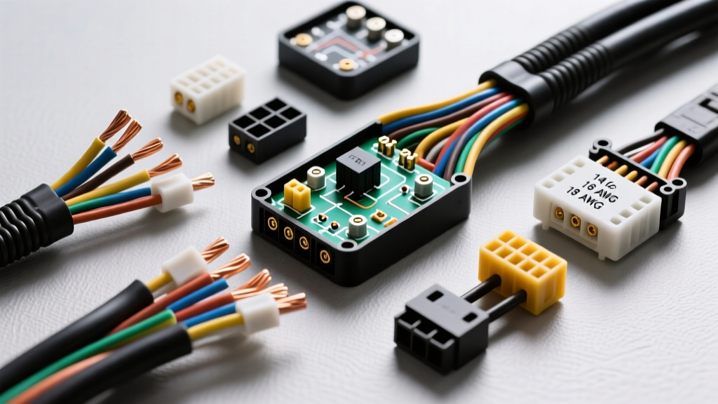
Architecture of the Auto Electric Ignition System
The auto electric ignition system serves as the primary sequenced power distribution node in a vehicle. It is far more than a simple mechanical switch; it manages high-amperage loads, ECU wake-up signals, and immobilizer authentication. In traditional column-mounted setups, the ignition switch acts as a heavy-duty rotary wafer switch. In modern vehicles, the auto electric ignition is a virtual state managed by the Body Control Module (BCM) and Passive Entry Passive Start (PEPS) networks. Understanding the exact wiring specifications, pinout configurations, and AWG requirements is critical for diagnosing no-crank, no-start, or parasitic draw conditions.
Traditional Ignition Switch Pinout and Terminal Specifications
For conventional steering column auto electric ignition assemblies (common in GM, Ford, and Chrysler platforms from 1995 to 2015), the switch typically features a 6-to-8 pin connector. The internal cam routes battery voltage to specific buses depending on the key cylinder position (OFF, ACC, RUN, START). Below is the standard specification chart for a typical 5-terminal ignition switch.
| Terminal | Function | Typical Wire Color (GM/Ford) | AWG | Max Continuous Load |
|---|---|---|---|---|
| BAT | Main Battery Feed | Red | 10 AWG | 40A (Fused) |
| ACC | Accessory Bus | Brown / Light Green | 14 AWG | 15A |
| IGN1 | Run/Start Bus (ECU, Fuel) | Pink / Dark Green | 14 AWG | 20A |
| IGN2 | Run Only (HVAC, Wipers) | Brown / White | 14 AWG | 15A |
| ST | Start Signal to Relay | Purple / Red-Light Blue | 12 AWG | 10A (Coil) |
Load Shedding During Crank
A critical design feature of the auto electric ignition switch is load shedding. When the key rotates to the START position, the mechanical cam physically breaks the ACC and IGN2 circuits. This disconnects high-draw accessories like the HVAC blower motor and windshield wipers, ensuring maximum battery voltage is available for the starter motor and the ECU's ignition coils.
The Starter Relay Control Circuit
The ST terminal rarely feeds the starter solenoid directly in modern applications. The starter solenoid's pull-in coil can draw an inrush current exceeding 30 amps, which would melt the 12 AWG ignition harness. Instead, the auto electric ignition ST feed triggers an ISO Mini Relay located in the under-hood fuse block.
- Pin 86 (Coil Feed): Ignition Start Feed from the ST terminal (Purple, 14 AWG).
- Pin 85 (Coil Ground): Ground or BCM Control (Black, 16 AWG). In newer vehicles, the BCM provides the ground path only after verifying the transmission is in Park/Neutral.
- Pin 30 (Contact Feed): Direct Battery Feed from the main fusible link (Red, 10 AWG).
- Pin 87 (Contact Output): Feeds the Starter Solenoid 'S' Terminal (Purple/Yellow, 12 AWG).
According to Delphi Technologies, a standard ISO mini relay coil resistance should measure between 65 and 85 ohms at room temperature. If your multimeter reads infinite resistance (OL), the coil is open, and the relay must be replaced.
Modern PEPS Auto Electric Ignition Architecture
In push-button start vehicles, the mechanical auto electric ignition switch is replaced by a momentary switch and a complex network of RF and LF antennas. The BCM validates the key fob using 125 kHz Low Frequency (LF) interior antennas to triangulate the fob's exact location, and a 315 MHz or 433 MHz UHF receiver for the signal return.
Once authenticated, the BCM sends a localized LIN bus (Local Interconnect Network) message to the Electronic Steering Column Lock (ESCL) module. The LIN bus operates at 19.2 kbps. The ESCL motor draws up to 8 amps during the unlock sequence. Upon successfully retracting the lock pin, the ESCL sends an "Unlocked" confirmation via the high-speed CAN bus to the BCM. Only then will the BCM internally ground the starter relay control circuit.
ESCL Voltage Drop Failure Mode
A common failure in PEPS auto electric ignition systems is a weak battery causing an ESCL reset. If the vehicle's battery voltage drops below 9.0V during the ESCL motor operation, the module may brown out and fail to send the CAN confirmation message. The BCM will inhibit the starter relay, resulting in a no-crank event, often accompanied by a "Steering Lock Malfunction" message on the dash.
Immobilizer Transponder Ring Antenna Specifications
In traditional keyed auto electric ignition systems, the immobilizer relies on a transponder ring antenna mounted directly over the key cylinder. This antenna operates at 125 kHz and powers the passive glass or carbon chip embedded in the key head via electromagnetic induction. The chip responds with a unique 32-bit or 48-bit cryptographic code. The antenna wiring typically consists of a twisted pair (often green and yellow, 22 AWG) connected to the Immobilizer Control Unit or the BCM. Because the signal voltage is in the millivolt range, this twisted pair must never be spliced with standard crimp connectors. Any break in the shielding or improper twisting will introduce EMI (Electromagnetic Interference) from the alternator, resulting in a "Security" light and a no-start condition.
Testing the Transponder Ring
Diagnosing the transponder ring requires an oscilloscope. Back-probe the antenna feed wire at the BCM connector while turning the key to the RUN position. You should observe a 125 kHz carrier wave burst lasting approximately 200 milliseconds, followed by the modulated response signal from the key. If the carrier wave is absent, check the 5V reference and ground circuits at the BCM. According to diagnostic procedures outlined by ASE certification standards, replacing the ring antenna requires a full immobilizer relearn procedure via an OEM-level bi-directional scan tool.
Diagnostic Voltage Drop Testing Matrix
When diagnosing voltage loss in the auto electric ignition circuit, never rely solely on resistance testing with an ohmmeter. A single strand of 10 AWG copper wire can show 0.1 ohms of continuity but still fail to carry 30 amps under load. Instead, perform dynamic voltage drop testing. According to SAE International standards for automotive electrical circuits, the maximum allowable voltage drop across any closed switch contact or connection is 0.2V.
| Test Point | Multimeter Setting | Expected Max Voltage Drop | Indication if Exceeded |
|---|---|---|---|
| BAT Terminal to IGN1 Terminal (Key in RUN) | DC Volts | 0.20V | Carbon tracking or pitted internal wafers |
| ST Terminal to Relay Pin 86 (Key in START) | DC Volts | 0.15V | Corroded harness connector or broken strands |
| Relay Pin 30 to Battery Positive (Cranking) | DC Volts | 0.10V | Undersized feed wire or fusible link degradation |
| ESCL Module Ground to Chassis (Unlocking) | DC Volts | 0.10V | Poor chassis ground star-point corrosion |
Parasitic Draw and Ignition Switch Isolation
A failing auto electric ignition switch is a frequent culprit behind intermittent parasitic battery draws. When the internal wafers become worn or contaminated with dielectric grease and metallic dust, the ACC or IGN1 circuits may fail to fully open when the key is removed. This leaves modules like the radio amplifier, HVAC control head, or telematics unit awake on the CAN bus.
To isolate the ignition switch during a parasitic draw test, connect a multimeter set to the 10A DC current setting in series with the negative battery terminal. Allow the vehicle to enter sleep mode (which can take up to 45 minutes on modern multiplexed networks). If the draw remains above the standard 50mA threshold, begin pulling fuses. If pulling the main IGN fuse drops the draw to normal levels, disconnect the ignition switch electrical connector. If the draw immediately drops, the switch's internal contacts are shorted. Always verify that the mechanical linkage between the key cylinder and the electrical switch is properly adjusted; a stretched linkage cable can prevent the switch from returning to the full OFF detent, leaving the accessory bus energized.
Summary of Best Practices
When repairing or bypassing any part of the auto electric ignition harness, always use oxygen-free copper (OFC) wire matching the original AWG specification. Never use T-taps or ScotchLoks on the IGN1 or ST circuits, as these connectors pierce the insulation and invite galvanic corrosion, leading to intermittent ECU brownouts or starter solenoid chatter. Use solder-seal heat shrink connectors and properly route the harness away from the exhaust manifold and steering column U-joints to ensure long-term electrical integrity.