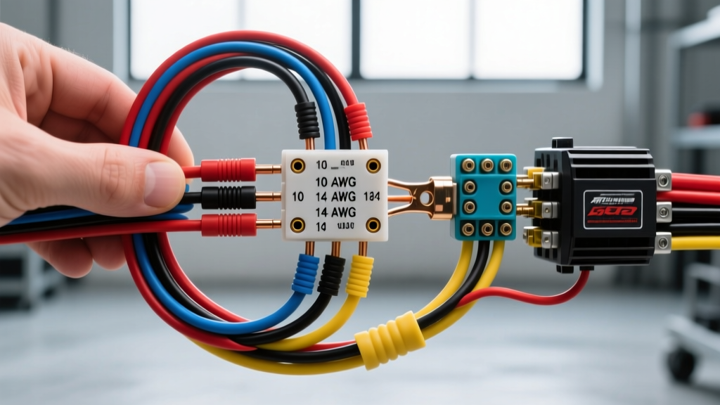
The Philosophy of High-Amp Restomod Architecture
When executing a modern engine swap or a full chassis restoration, relying on factory 14-gauge wiring is a recipe for melted insulation and catastrophic electrical fires. The Williams Auto Electric methodology has become the gold standard in the custom hot rod and restomod community. This approach prioritizes military-grade bulkhead connectors, high-temperature cross-linked wiring, and centralized power distribution to safely handle the 140A+ alternator outputs demanded by modern EFI systems, electric power steering (EPS), and PWM cooling fans.
In this upgrade and modification guide, we break down the core principles of the Williams Auto Electric harness building technique, providing you with the exact AWG specifications, pinout configurations, and crimping protocols required to build a show-quality, bulletproof electrical architecture for your project vehicle.
SAE J1128 Wire Selection: GXL vs. Standard PVC
The foundation of any premium custom harness is the wire itself. Standard PVC (polyvinyl chloride) primary wire begins to degrade at temperatures above 105°C (221°F). Under-hood environments in restomods, especially those with tight exhaust headers and turbochargers, routinely exceed this. The Williams Auto Electric method strictly mandates the use of SAE J1128 compliant GXL (General Cross-Linked) or TXL (Thin-Wall Cross-Linked) wire.
GXL wire features a cross-linked polyethylene (XLPE) insulation that withstands continuous temperatures up to 125°C (257°F) and offers superior resistance to automotive fluids, acids, and abrasion. Furthermore, the thin-wall insulation of TXL/GXL allows for smaller harness diameters, making it easier to route through tight firewall grommets and vintage dash cavities while maintaining the same copper cross-section and ampacity as thicker PVC wire.
Table: Restomod Wire Gauge & Ampacity Chart (GXL/TXL)
| AWG Size | Strand Count | Max Ampacity (Engine Bay) | Primary Restomod Application | Recommended Fuse/Breaker |
|---|---|---|---|---|
| 1/0 AWG | 2107 | 245A | Battery relocation, Main starter feed | 250A ANL / Mega Fuse |
| 4 AWG | 567 | 120A | High-amp alternator output (100A-120A) | 150A Mega Fuse |
| 10 AWG | 147 | 40A | PWM Fan relays, EPS power feeds | 40A ATO / Circuit Breaker |
| 14 AWG | 41 | 20A | Headlight relays, Fuel pump primary | 20A ATO |
| 18 AWG | 16 | 7A | ECM sensor signals, CAN-Bus lines | 5A Mini Fuse |
Firewall Bulkhead Integration & Pinout Strategy
One of the most defining characteristics of a Williams Auto Electric style build is the elimination of messy, drip-loop wiring passes through the firewall. Instead, high-end restomods utilize sealed, multi-pin bulkhead connectors. The Deutsch DTM series or Packard Weather-Pack 56 series are preferred due to their secondary lock wedges and silicone weather seals, which prevent moisture ingress and terminal oxidation.
When designing a 24-circuit bulkhead pass-through, it is critical to segregate high-amperage power feeds from sensitive ECM sensor signals to prevent Electromagnetic Interference (EMI). Below is a standardized pinout strategy for a modern V8 EFI restomod utilizing a 24-pin Deutsch DTM bulkhead.
Table: 24-Circuit Deutsch DTM Bulkhead Pin Assignment
| Pin # | Wire Color | AWG | Function / Circuit Description | Connector Type |
|---|---|---|---|---|
| 1 | Red | 10 | Switched 12V+ (Ignition Run/Start) | DTM Size 16 |
| 2 | Yellow | 14 | ECM Main Relay Trigger | DTM Size 16 |
| 3 | Purple | 14 | Starter Solenoid 'S' Terminal Trigger | DTM Size 16 |
| 4-5 | Blue/White | 18 | CAN-High / CAN-Low (Twisted Pair) | DTM Size 20 |
| 6-8 | Black | 12 | Sensor Ground Returns (ECM Dedicated) | DTM Size 16 |
| 9 | Green | 18 | O2 Sensor Signal (Bank 1) | DTM Size 20 |
| 10 | Gray | 18 | Tachometer Output (ECM) | DTM Size 20 |
Note: Always use a ratcheting crimp tool (such as the Hozan P-707 or TE Connectivity Amp-Lance) for Deutsch terminals. A proper crimp will yield a gas-tight connection, pulling the wire insulation into the support barrel for maximum strain relief.
EFI Integration & PWM Cooling Fan Relays
Modern engine management systems, such as those detailed in the Holley EFI Wiring Manual, require clean, noise-free power. Voltage spikes from inductive loads like cooling fans and fuel pumps can corrupt ECM data logs or cause misfires. The Williams Auto Electric protocol dictates that no high-draw component should be switched directly by the ECM or a dash toggle.
Instead, use Bosch-style 5-pin ISO mini relays. The ECM or PWM fan controller only switches the low-amperage ground path (Pin 85), while the high-amperage load flows directly from the battery through a dedicated fuse block to Pin 30, and out to the component via Pin 87.
- Pin 30: 12V+ Battery Feed (Fused at source, 10 AWG wire)
- Pin 87: Normally Open (NO) Output to Load (10 AWG wire to fans)
- Pin 87a: Normally Closed (NC) - Unused in this application, snip and seal
- Pin 86: 12V+ Ignition Switched Feed (14 AWG wire)
- Pin 85: Coil Ground / Trigger (18 AWG wire to ECM/PWM Controller)
To prevent voltage spikes when the relay coil collapses, wire a 1N4001 flyback diode across Pins 85 and 86, with the diode stripe facing Pin 86. This clamps the inductive spike and protects sensitive solid-state ECM drivers.
Alternator Excitation & High-Amp Upgrades
Upgrading from a stock 65A alternator to a 140A+ unit (like a Powermaster or Mechman) requires more than just a thicker main output wire. Many modern high-amp alternators utilize a 3-wire or 4-wire configuration to sense voltage accurately and prevent overcharging. If you use a 1-wire setup, the alternator relies on internal voltage sensing at the rear terminal, which often results in the battery undercharging at idle due to voltage drop across the harness.
For a proper restomod upgrade, wire the alternator's 'S' (Sense) terminal directly to the positive battery post or main distribution block using a dedicated 14 AWG red wire. Wire the 'L' (Lamp/Excitation) terminal to a 12V ignition-switched source through a 56-ohm resistor or an LED dash indicator light. This ensures the alternator excites immediately upon startup and regulates voltage precisely where it matters most: at the battery.
The Zero-Voltage-Drop Grounding Protocol
The most common cause of erratic EFI behavior, flickering gauges, and hard starting in restomods is poor grounding. The Williams Auto Electric method treats the ground circuit with the exact same importance as the positive power feed. Never rely on sheet metal or rusty chassis bolts for high-amperage grounds.
- Surface Preparation: Use a wire wheel or sandpaper to strip paint, powder coat, and rust down to bare, shiny metal at every ground termination point.
- Terminal Selection: Use only seamless, adhesive-lined ring terminals. Avoid open-spade or fork terminals on high-vibration chassis points.
- Hardware: Use Grade 8 or stainless steel bolts with a star washer placed between the bare metal and the ring terminal to bite into the chassis. Apply dielectric grease over the completed connection to prevent galvanic corrosion.
- Torque Specs: Torque M8 ground studs to 22 Nm (16 lb-ft) to ensure maximum surface area contact without stripping the threads.
For engine-to-chassis grounds, use a minimum of 2 AWG flexible welding cable with heavy-duty copper lugs, crimped and sealed with 3:1 ratio dual-wall heat shrink to prevent acid wicking via capillary action.
Troubleshooting Voltage Drop & Parasitic Draw
Even with meticulous planning, restomod projects can develop electrical gremlins. Use the following diagnostic tree to isolate common high-amp upgrade issues.
| Symptom | Probable Cause | Diagnostic Fix / Action |
|---|---|---|
| Battery voltage drops to 12.8V at idle, but reads 14.2V at 2000 RPM. | Alternator is in 1-wire mode or 'S' sense wire is missing/loose. | Verify 14 AWG sense wire from Alt 'S' terminal directly to Battery (+). Check for voltage drop across main 4 AWG alt cable. |
| ECM resets or datalog cuts out when PWM cooling fans engage. | Inductive voltage spike or shared sensor ground. | Install 1N4001 flyback diodes on fan relays. Ensure ECM grounds are dedicated (star-grounded) and not shared with fan motors. |
| Starter clicks once, dash lights dim, engine fails to crank. | High resistance on main starter feed or poor engine block ground. | Perform a voltage drop test across the main 1/0 AWG battery cable during crank. Replace engine-to-frame ground strap. |
| Parasitic draw exceeds 50mA with key off and ECM asleep. | Alternator diode trio failure or aftermarket radio memory wire routed incorrectly. | Pull the 150A Mega Fuse on the alternator feed. If draw drops, replace alternator. Check for fused constant 12V feeds bypassing the ignition switch. |
Final Looming and Harness Protection
To achieve the signature Williams Auto Electric aesthetic and durability, avoid cheap corrugated plastic split-loom. Instead, wrap the completed harness sections in high-temperature nylon braided sleeving or Teflon (PTFE) tape. Secure the harness to the chassis using stainless steel Adel clamps (cushion clamps) spaced no more than 12 inches apart, ensuring the harness never rests directly against exhaust components or sharp sheet metal edges. By adhering to these stringent architectural standards, your restomod will not only look like a professional build but will deliver reliable, noise-free electrical performance for decades.