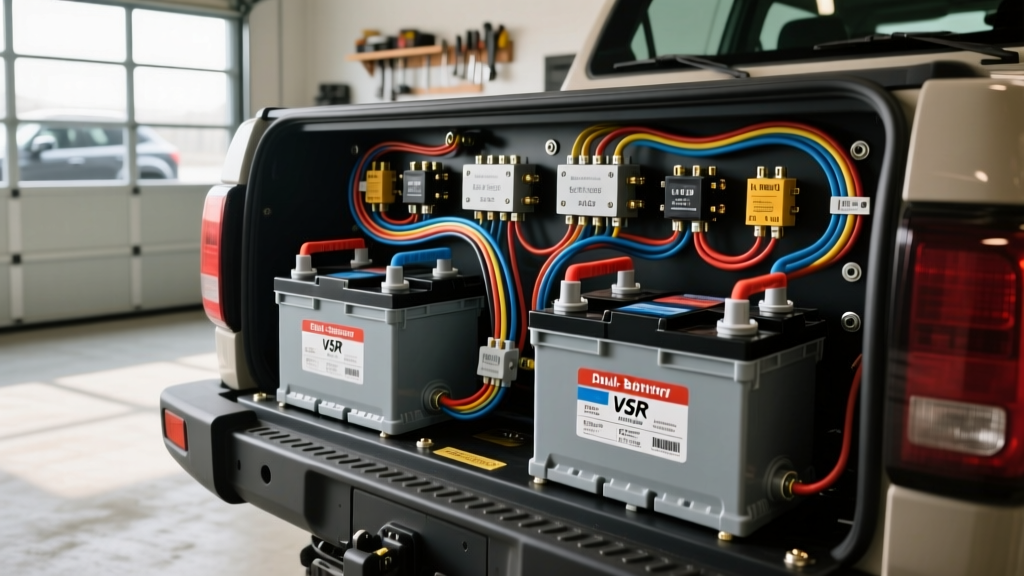
Understanding the 12 Volt Dual Battery Wiring Diagram
When outfitting an overland vehicle or off-grid camper, a robust auxiliary power system is non-negotiable. Running fridge compressors, lighting, and inverters directly off your starter battery is a guaranteed way to strand yourself in the backcountry. A properly executed 12 volt dual battery wiring diagram isolates your engine-cranking battery from your house loads while allowing the alternator to charge both banks simultaneously. However, simply throwing a relay and some cables under the hood is a recipe for voltage drop, melted insulation, or a fried alternator diode pack. This guide provides a master-level, practical installation protocol for setting up a high-current dual battery system using modern Voltage Sensitive Relays (VSR) or DC-DC chargers.
Phase 1: Topology Selection and Component Sizing
Before cutting any wire, you must define the topology of your 12 volt dual battery wiring diagram. The two most common modern solutions are the VSR (Voltage Sensitive Relay) and the DC-DC Battery Charger.
- VSR (Voltage Sensitive Relay): Ideal for identical battery chemistries (e.g., AGM to AGM). The VSR monitors the starter battery voltage. When the alternator pushes the voltage above 13.7V, the internal solenoid engages, paralleling the batteries. When voltage drops below 12.8V (engine off), it disconnects, protecting the cranking battery.
- DC-DC Charger: Mandatory if mixing chemistries (e.g., Lead-Acid starter to Lithium LiFePO4 auxiliary). It steps down or regulates alternator output to provide a multi-stage charging profile, protecting the alternator from the massive inrush current that a depleted lithium battery can demand.
Cable Sizing and ABYC Standards
Automotive wire sizing must account for total round-trip circuit length, not just the one-way distance from the battery to the load. According to Blue Sea Systems and ABYC E-11 standards, voltage drop should not exceed 3% for critical charging circuits. Below is the specification chart for high-current inter-battery links.
| Max Amperage | One-Way Run Length | Recommended AWG | Insulation Type | Terminal Style |
|---|---|---|---|---|
| 150A | Under 5 ft | 2 AWG | SGT / Welding Cable | 3/8" Tinned Copper Ring |
| 150A | 5 ft - 10 ft | 1/0 AWG | SGT / Welding Cable | 3/8" Tinned Copper Ring |
| 200A+ | 10 ft - 15 ft | 2/0 AWG | SGT / Welding Cable | 1/2" Tinned Copper Ring |
| Ignition Sense | Any Length | 14 AWG | TXL / GXL | 1/4" Spade / Heat Shrink |
Phase 2: Grounding and Battery Tray Preparation
The most common failure point in any 12 volt dual battery wiring diagram is the ground return path. Do not rely on factory chassis grounds for high-current auxiliary links.
- Surface Preparation: Remove the auxiliary battery tray. Use a 3M Scotch-Brite pad or 120-grit sandpaper to remove paint, powder coating, and rust down to bare, shiny metal at the designated grounding point.
- Corrosion Inhibition: Apply a thin layer of Noalox or marine-grade anti-corrosion grease to the bare metal before placing the terminal. This prevents oxidation from forming under the lug, which increases resistance and causes heat.
- Hardware: Use a Grade 8 or stainless steel bolt, paired with a flat washer and a star lock washer. The star washer bites into the metal to ensure a vibration-proof, low-resistance connection.
- Final Seal: Once torqued to spec (typically 15-20 Nm for M8 chassis bolts), coat the entire lug and exposed metal with dielectric grease or liquid electrical tape to seal out moisture and road salt.
Phase 3: Routing High-Current Cables and Fusing
When routing the main positive cables (Red SGT wire) from the starter battery to the auxiliary battery or VSR, physical protection is paramount. Route cables away from exhaust manifolds, steering shafts, and sharp firewall edges. Use split-loom tubing and secure it with UV-resistant zip ties every 8 inches. Where cables pass through the firewall or bulkheads, always use heavy-duty rubber grommets.
Overcurrent Protection Placement
Fuses protect the wire, not the component. According to Victron Energy's Wiring Unlimited guidelines, the main overcurrent protection device (OCPD) must be installed as close to the power source as possible.
- Starter Battery Side: Install a Class T or ANL fuse within 7 inches of the positive battery post. Class T fuses are preferred for lithium systems or high-surge environments due to their high interrupt capacity (AIC) of up to 20,000 amps.
- Auxiliary Battery Side: Install a second identical fuse within 7 inches of the auxiliary battery positive post. This protects the wire in the event the auxiliary battery shorts to ground or backfeeds during a VSR failure.
Phase 4: VSR Mounting and Ignition Sense Wiring
If your 12 volt dual battery wiring diagram utilizes a smart VSR or a DC-DC charger with an ignition-sense trigger, the control wire routing is critical.
- Mounting: Mount the VSR/DC-DC unit on a cool, well-ventilated surface. These units generate significant heat during bulk charging phases. Keep them away from the exhaust side of the engine bay.
- Ignition Sense Connection: Run a 14 AWG yellow TXL wire from the VSR's ignition sense terminal to an ignition-switched 12V source in the fuse box (e.g., the wiper or radio fuse circuit). Use an Add-A-Circuit (fuse tap) that places the new fuse on the "load" side of the factory fuse to prevent backfeeding.
- Alternator Protection: The ignition sense wire ensures the VSR does not attempt to parallel the batteries immediately upon engine start. It waits until the alternator is actively producing voltage, preventing the massive combined surface-charge inrush from stalling the engine or slipping the alternator belt.
Phase 5: Crimping and Torque Specifications
For 2 AWG and larger cables, soldering is strictly prohibited in high-vibration automotive environments. Solder wicks into the wire strands, creating a rigid point that will eventually suffer from copper fatigue and snap under engine vibration. Instead, use closed-barrel hex crimps or high-quality tinned copper ring terminals.
- Tooling: Use a hydraulic or heavy-duty ratcheting hex crimper. A hex crimp deforms the terminal evenly around the wire, ensuring maximum surface area contact and a gas-tight seal.
- Heat Shrink: Use dual-wall, adhesive-lined marine heat shrink (typically 3:1 or 4:1 shrink ratio). When heated, the inner meltable adhesive layer oozes out the ends, creating a waterproof seal that prevents capillary action from drawing battery acid or moisture up into the copper strands.
- Battery Terminal Torque: Over-tightening lead or brass battery posts will strip them or crack the battery casing. Torque standard top-post battery clamps to 8-10 Nm (approx. 70-90 in-lbs). For side-post GM style batteries, torque to 11-14 Nm.
Troubleshooting Decision Tree: Common Dual Battery Failures
Even with a perfect 12 volt dual battery wiring diagram on paper, real-world variables can cause issues. Use this matrix to diagnose common installation faults.
| Symptom | Probable Cause | Diagnostic Step / Fix |
|---|---|---|
| VSR clicks rapidly on and off while idling. | Voltage drop across the main interconnect cables is too high, causing the VSR to read below the 12.8V disconnect threshold under load. | Measure voltage at both batteries while idling. If delta is >0.5V, upgrade from 2 AWG to 1/0 AWG or clean corroded ground lugs. |
| Auxiliary battery never reaches 100% SOC. | VSR paralleling does not provide an absorption/float stage, or wire resistance is dropping the charge voltage below 13.2V at the aux battery. | Switch to a multi-stage DC-DC charger to properly condition AGM/Lithium banks and compensate for line loss. |
| Alternator whining or belt squealing on startup. | Massive inrush current from a deeply depleted auxiliary battery is overloading the alternator diodes or slipping the belt. | Install an alternator protection module or switch to a current-limited DC-DC charger (e.g., 40A max draw). |
| ANL Fuse blows instantly upon engine start. | Combined surface charge and starter motor draw exceeding fuse rating, or short to ground on the main positive cable. | Verify cable routing for pinch points. Upgrade to a Class T fuse which handles high transient DC surges better than ANL. |
Final Validation and SAE Compliance
Once all connections are made, perform a final validation sweep. Use a digital multimeter to verify continuity on the ignition sense circuit and check for stray voltage on the chassis. Ensure all cables meet SAE J1128 specifications for low-tension primary cable, which mandates specific insulation thickness and temperature ratings (up to 125°C for under-hood routing). A meticulously executed dual battery system will provide years of reliable off-grid power, keeping your fridge cold and your starter battery fully charged, no matter how far off the grid you travel.