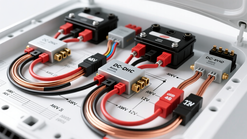
Architecture Overview: Dual-Voltage 12V/48V Systems
The transition from traditional 12-volt electrical systems to dual-voltage architectures is one of the most significant shifts in modern automotive and marine engineering. Whether you are designing a Mild Hybrid Electric Vehicle (MHEV) belt-driven starter-generator (BSG) system, an off-grid 48V LiFePO4 solar array, or a heavy-duty marine winch setup, understanding the 12V and 48-volt battery wiring diagram is critical. A dual-voltage system utilizes a 48V loop to handle high-current loads (e.g., electric A/C compressors, e-turbos, high-wattage inverters) while maintaining a 12V loop for legacy ECUs, infotainment, and lighting.
Wiring these two distinct voltage domains requires strict adherence to isolation protocols, precise AWG (American Wire Gauge) sizing, and specialized overcurrent protection. Because 48V systems operate at roughly four times the voltage of a standard 12V system, they draw 75% less current for the same wattage. However, the insulation requirements and DC interrupt capacities for fusing change drastically. This technical specification reference outlines the exact wiring topologies, color codes, and hardware requirements for integrating a safe, high-efficiency 12V/48V dual battery system.
Load Calculation & AWG Sizing Matrix
The primary advantage of a 48V architecture is the reduction in copper mass and I²R (heat) losses. When sizing cables for a 12V and 48-volt battery wiring diagram, engineers must calculate the maximum continuous amperage and apply a 125% safety multiplier per standard marine and automotive electrical codes. Below is a comparative AWG sizing matrix for common dual-voltage loads, assuming a 3% maximum voltage drop over a 10-foot (3-meter) one-way cable run.
| Load Wattage | 12V System Current (A) | 12V AWG Size (3% Drop) | 48V System Current (A) | 48V AWG Size (3% Drop) | Copper Mass Reduction |
|---|---|---|---|---|---|
| 1,000W | 83.3A | 2 AWG | 20.8A | 10 AWG | ~85% |
| 2,000W | 166.6A | 1/0 AWG | 41.6A | 6 AWG | ~88% |
| 3,000W | 250.0A | 2/0 AWG | 62.5A | 4 AWG | ~89% |
| 5,000W | 416.6A | 3/0 AWG (Dual Run) | 104.1A | 1 AWG | ~92% |
Note: Amperage calculations assume nominal voltages (12.0V and 48.0V). Always size fusing based on the wire's ampacity, not just the load.
12V and 48-Volt Battery Wiring Diagram Topology
A properly engineered dual-voltage schematic physically and electrically separates the high-power 48V traction/accessory loop from the sensitive 12V control loop. They are bridged only by a bidirectional or unidirectional isolated DC-DC converter.
48V High-Current Traction & Accessory Loop
The 48V battery bank (typically LiFePO4 or NMC lithium chemistry in modern applications) connects directly to a heavy-duty main disconnect switch. From the disconnect, the positive feed routes to a Class T Fuse (JLLN series). Standard ANL or Mega fuses are strictly prohibited on large 48V lithium banks; lithium cells can deliver short-circuit currents exceeding 5,000A, which will cause an ANL fuse (rated for ~2,700 AIC) to sustain a DC plasma arc. Class T fuses offer a 20,000 Ampere Interrupting Capacity (AIC) at 160VDC, safely extinguishing the arc.
Post-fuse, the 48V positive routes to a solid copper busbar (tin-plated). High-current loads, such as a 48V-to-120V/240V inverter or an electric power steering (EPS) pump, draw directly from this busbar using high-strand-count, flexible silicone-insulated wire.
DC-DC Step-Down & 12V Auxiliary Loop
The 12V system is sustained by an isolated DC-DC converter (e.g., 48V input to 12V output, rated 60A to 100A). The 48V feed to the DC-DC converter must be fused independently at the source busbar. The 12V output of the converter feeds into a secondary 12V automotive fuse panel (using standard ATO/ATC or Maxi fuses). This 12V panel distributes power to the ECU, CAN bus transceivers, lighting, and telemetry. By utilizing an isolated DC-DC converter rather than a non-isolated buck converter, you ensure that a catastrophic failure on the 48V side cannot send 50+ volts down the 12V rail and fry the vehicle's engine management computer.
OEM Color Codes & Insulation Standards
Adhering to standardized color codes prevents lethal or destructive cross-wiring during maintenance. While 48V nominal (which peaks at 58.4V when fully charged) technically falls just below the 60V DC threshold defined as 'High Voltage' by OSHA and SAE, automotive OEMs treat it with high-voltage protocols to prevent 12V/48V mixing.
- 12V Positive: Red (per SAE J1128 Low Tension Cable standards).
- 12V Negative/Ground: Black.
- 48V Positive: High-Voltage Orange (per SAE J1673) or Red with an Orange tracer. Modern MHEV manufacturers (e.g., Audi, Porsche) exclusively use Orange for 48V MHEV harnesses.
- 48V Negative: Black with an Orange tracer, or solid Orange with a black stripe.
- CAN Bus / Data: Twisted pair, typically Yellow/Green or Shielded Silver, kept physically separated from 48V power lines by at least 50mm to prevent Electromagnetic Interference (EMI).
Insulation Rating: Standard 12V automotive wire (GXL/TXL) is rated for 60V. For the 48V loop, you must use wire rated for a minimum of 600V (such as TXL 600V or marine-grade UL 1426) to handle voltage spikes and inductive kickback from 48V motors and contactors.
Connector Selection & Torque Specifications
Standard 12V automotive terminals (ring terminals, spade connectors) are insufficient for 48V high-current nodes. Vibration and thermal cycling will cause standard crimps to loosen, leading to high-resistance arcing at 48V.
| Application | Recommended Connector | Voltage/Current Rating | Hardware & Torque Spec |
|---|---|---|---|
| 48V Battery to Busbar | Amphenol SurLok Plus (SLPIPA) | 1000V DC / 200A | M8 Bolt, 18-22 Nm |
| 48V Inverter / Motor | Anderson SB175 / SB350 | 600V DC / 175A-350A | M6/M8, 12-18 Nm |
| 12V DC-DC Output | Heavy-Duty Ring Terminal (Heat Shrink) | 60V DC / 100A | M8 Bolt, 18-22 Nm |
| 12V ECU / Sensors | Deutsch DT / DTM Series | 250V DC / 13A | N/A (Push-pin lock) |
When terminating 48V high-current lugs to copper busbars, always apply a thin layer of anti-oxidant compound (e.g., NO-OX-ID A-Special) to prevent galvanic corrosion, especially in marine or high-humidity environments. Use a calibrated torque wrench; over-torquing M8 brass or copper terminals will stretch the bolt and result in a loss of clamping force during thermal expansion.
Grounding Topologies & Fault Isolation
One of the most common failure modes in dual-voltage systems is improper grounding. In a standard 12V vehicle, the chassis serves as the common ground return. In a 48V MHEV or marine environment, utilizing the chassis for 48V return currents can lead to severe stray current corrosion and EMI issues.
According to ABYC E-11 AC & DC Electrical Systems on Boats and modern automotive OEM guidelines, the 48V negative return should be an isolated, dedicated copper ground busbar routed directly back to the 48V battery negative terminal (a 'home run' ground). The 12V system may use the chassis ground. The two ground systems (12V chassis and 48V isolated busbar) should only be bonded at a single star-point near the DC-DC converter. This single-point bond ensures that the 12V and 48V systems share a common reference voltage for the CAN bus and telemetry, while preventing high-frequency 48V return currents from backfeeding through the 12V ECU ground planes.
Troubleshooting Voltage Drop and Cross-Contamination
When diagnosing faults in a 12V and 48-volt battery wiring diagram, technicians must use a True-RMS digital multimeter (DMM) rated for CAT III 600V minimum. Standard automotive test lights and low-voltage meters can fail catastrophically if accidentally connected across a 48V or 58V source.
Symptom-Cause-Fix Decision Tree
- Symptom: 12V ECU resets or throws low-voltage codes when 48V high-load (e.g., winch or inverter) engages.
- Cause: Non-isolated DC-DC converter or shared ground bus causing 48V voltage sag to pull the 12V reference ground below ECU thresholds.
- Fix: Upgrade to a galvanically isolated DC-DC converter and verify the single-point star ground topology.
- Symptom: Burning smell or melted insulation at 48V busbar connections.
- Cause: Improper torque on Amphenol SurLok or ring terminals, leading to micro-arcing and increased contact resistance.
- Fix: Cut back damaged wire, re-crimp using a hex-die hydraulic crimper, apply anti-oxidant paste, and torque to 20 Nm.
- Symptom: CAN bus communication errors (U-codes) across the vehicle network.
- Cause: 48V positive cables routed parallel to unshielded CAN bus wiring, inducing high-frequency EMI.
- Fix: Re-route 48V cables to maintain a minimum 50mm (2-inch) separation from data lines, or wrap data lines in braided copper shielding tied to a clean 12V ground.
By strictly adhering to these AWG specifications, isolation protocols, and OEM-level color coding, you ensure that your dual-voltage architecture operates efficiently, safely, and free from the cross-contamination issues that plague poorly designed 12V/48V integrations.