Choosing the Right Camper Battery Wiring Diagram for Your Build
When planning an off-grid vehicle build, selecting the correct camper battery wiring diagram is the difference between a reliable power system and a persistent electrical fire hazard. A wiring diagram is not just a visual map; it dictates your component selection, AWG wire sizing, and overcurrent protection strategy. In the automotive and RV electrical space, generic diagrams often fail to account for the massive inrush currents of modern inverters or the strict charging profiles required by lithium iron phosphate (LiFePO4) cells.
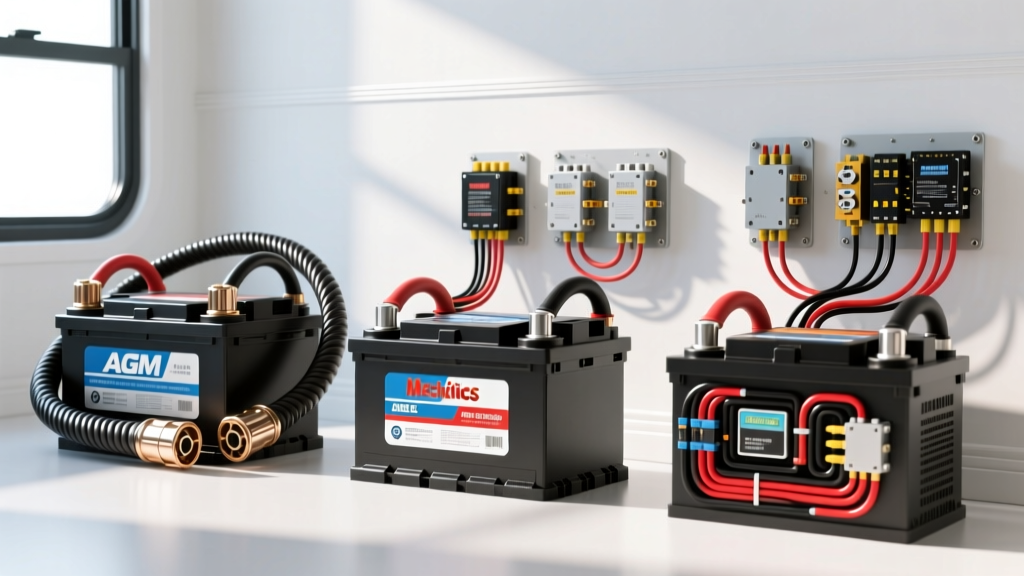
As an automotive electrical specialist, I evaluate camper battery wiring diagrams based on three core metrics: continuous current capacity, voltage drop mitigation, and adherence to ABYC E-11 marine/RV standards. Below, we compare the three most common camper battery topologies, breaking down the exact wire gauges, fuse types, and busbar configurations required for each.
Configuration 1: Basic AGM/Lead-Acid Setup (Entry-Level Diagram)
The entry-level camper battery wiring diagram centers around a single or dual-bank Absorbed Glass Mat (AGM) battery paired with a basic PWM solar charge controller and a standalone 1000W inverter. This topology is straightforward but requires heavy cabling due to the voltage sag inherent in lead-acid chemistry under load.
Technical Specifications & Component Selection
- Battery Bank: 2x 100Ah AGM Batteries (Wired in parallel).
- Interconnect Cables: 2/0 AWG pure copper, 12 inches max length to minimize resistance between parallel cells.
- Main Overcurrent Protection: 250A ANL Fuse on the positive main trunk. AGM batteries have lower short-circuit current limits compared to lithium, making ANL fuses sufficient and cost-effective.
- Busbars: Blue Sea Systems 2150 (250A continuous rating) with 5/16" (M8) studs.
- Wire Routing: 2 AWG welding cable for the inverter run (up to 10 feet). Voltage drop must be kept under 3%.
Pros and Cons
This diagram is highly forgiving regarding BMS integration and alternator charging. However, AGM batteries should only be discharged to 50% Depth of Discharge (DoD). If you attempt to pull 1500W from a microwave, the voltage will sag below the inverter's Low Voltage Disconnect (LVD) threshold of 10.5V, causing an immediate system shutdown despite having 'usable' capacity remaining.
Configuration 2: Lithium LiFePO4 with DC-DC & Smart Shunt (Advanced Diagram)
The modern standard for camper builds utilizes a 12V LiFePO4 battery bank, a Bluetooth-enabled smart shunt, and a DC-DC alternator charger. This camper battery wiring diagram is significantly more complex, requiring dedicated ignition-sense wiring and precise BMS communication protocols to protect the vehicle's alternator from thermal failure.
Technical Specifications & Component Selection
- Battery Bank: 1x 200Ah LiFePO4 (Internal BMS with 100A continuous discharge limit).
- Main Overcurrent Protection: 150A Class T Fuse. Lithium batteries can deliver massive fault currents (upwards of 3,000A) in a short circuit. A Class T fuse provides the necessary fast-blow interrupt rating (AIC of 20,000A) that standard ANL fuses lack.
- DC-DC Charger: Victron Orion-Tr Smart 12/12-30A. Requires 6 AWG wire for the alternator input. Crucially, Pin 4 on the Orion's connector must be tied to the vehicle's ignition circuit (12V+ only when running) to prevent parasitic drain and alternator overload at idle.
- Monitoring: Victron SmartShunt 500A/50mV. The VE.Direct port allows telemetry integration, while the auxiliary input can monitor the starter battery or mid-point voltage.
Pros and Cons
This diagram provides 80-100% usable DoD and maintains a flat voltage curve (13.4V - 13.6V) under heavy loads. The primary drawback is the strict alternator wiring requirement; failing to route the ignition sense wire correctly will cause the DC-DC charger to pull 30A from the alternator even when the engine is off, or overwork the alternator at low RPMs.
Configuration 3: High-Power Hybrid Inverter System (Pro Diagram)
For campers running induction cooktops, roof air conditioners, and electric water heaters, the wiring diagram shifts to a 48V architecture or a massive 12V 3000W+ hybrid inverter/charger. We will focus on the 12V high-current variant, which demands extreme attention to terminal torque and thermal management.
Technical Specifications & Component Selection
- Battery Bank: 2x 12V 300Ah LiFePO4 in parallel (600Ah total).
- Cabling: 4/0 AWG (0000 AWG) pure copper for all main battery-to-busbar and busbar-to-inverter runs. 4/0 AWG is rated for 260A continuous in engine spaces, but for a 3000W inverter pulling 250A at 12V, you must derate for bundling and ambient heat.
- Busbars: Blue Sea Systems 8260 Heavy Duty Busbar (600A continuous rating) with 3/8" (M10) studs. Standard 250A busbars will melt under sustained 250A inverter loads.
- Lugs & Termination: Tinned copper ring terminals with a 3:1 adhesive-lined heat shrink ratio. Untinned aluminum lugs will suffer from galvanic corrosion when mated to copper busbars in humid camper environments.
Pros and Cons
This topology supports massive surge loads (up to 6000W for 3 seconds) required for compressor startups. However, the physical execution of the camper battery wiring diagram is difficult; 4/0 AWG wire has a large bend radius and requires specialized hex-crimp tools. Poor crimps on 4/0 AWG lugs are the leading cause of thermal fires in high-power RV builds.
Component Selection Matrix: Busbars, Fuses, and Lugs
Matching your components to your chosen diagram is critical. Use the table below to select the correct hardware based on your system's maximum continuous amperage.
| System Type | Max Continuous Draw | Busbar Recommendation | Main Fuse Type | Wire Gauge (Main Trunk) |
|---|---|---|---|---|
| Basic AGM (1000W Inv) | 125A | Blue Sea 2150 (250A) | 150A ANL | 2 AWG |
| Lithium DC-DC (2000W Inv) | 180A | Blue Sea 2150 (250A) | 200A Class T | 1/0 AWG |
| High-Power (3000W+ Inv) | 280A+ | Blue Sea 8260 (600A) | 300A Class T | 4/0 AWG |
Reference: For detailed fault-current interrupt ratings, consult the Blue Sea Systems DC Circuit Protection Guide.
ABYC & SAE Wiring Standards for Campers
Automotive SAE standards and marine/RV ABYC E-11 standards often conflict regarding wire color codes. For a camper that bridges both worlds, adhering to ABYC E-11 is the safest route to prevent fatal AC/DC wiring confusion.
- DC Positive: Must be Red.
- DC Negative (Ground): Must be Yellow, or Black with a Yellow Stripe. (Using solid black for DC ground is dangerous in RVs, as Black is the standard color for 120V AC 'Hot' lines in North America).
- Ignition Sense / Switched 12V: Blue or White.
- Terminal Torque Specs: Torque is rarely specified in amateur camper battery wiring diagrams, but it is vital. For 5/16" (M8) busbar studs, torque to 84-96 in-lbs (7-8 ft-lbs). For 3/8" (M10) studs, torque to 120-144 in-lbs (10-12 ft-lbs). Use a calibrated inch-pound torque wrench; overtightening will strip the soft copper threads of the busbar, while undertightening creates high-resistance hot spots.
For comprehensive topology planning and voltage drop calculations, the Victron Energy Wiring Unlimited Manual remains the industry gold standard for off-grid electrical design.
Troubleshooting Common Diagram Execution Errors
Even with a perfect camper battery wiring diagram on paper, physical execution errors are common. Here is a decision tree for diagnosing the top three high-current wiring failures:
1. Inverter Shuts Down Under Heavy Load (Voltage Drop)
- Symptom: Inverter displays 'Low Voltage' alarm at 11.2V when the microwave turns on, but battery monitor reads 13.2V.
- Cause: High resistance between the battery terminal and the inverter DC input. The voltage is dropping across the wire or a bad crimp.
- Fix: Perform a millivolt drop test across each connection point while under load. A good crimp and connection should drop less than 10mV. If a connection drops 50mV+, cut off the lug, strip the wire back to bare copper, and re-crimp using a proper hex-die tool.
2. Smart Shunt Shows Incorrect State of Charge (SoC)
- Symptom: Victron SmartShunt reads 100% but batteries are dead, or reads 0% when fully charged.
- Cause: The shunt's negative sense wire (the small red wire with the inline fuse) is connected to the wrong side of the shunt, or a load is bypassing the shunt entirely.
- Fix: In your wiring diagram, ALL DC negative loads and charger negatives MUST route through the 'Load/Charger' side of the shunt. The 'Battery Minus' side must connect ONLY to the battery bank negative. Verify the small sense wire is connected to the correct M10 bolt.
3. Alternator Whine or DC-DC Charger Overheating
- Symptom: DC-DC charger casing is too hot to touch, or vehicle alternator voltage fluctuates wildly.
- Cause: Using undersized wire (e.g., 8 AWG instead of 6 AWG) for the 30A DC-DC alternator input, causing the charger to operate at maximum duty cycle to compensate for voltage drop.
- Fix: Upgrade the alternator-to-charger wiring to 4 AWG or 6 AWG, and ensure the chassis ground return path is equally robust. Never rely on the vehicle's thin sheet metal for a high-amperage DC-DC ground return; run a dedicated negative cable back to the battery or a dedicated 250A ground busbar.