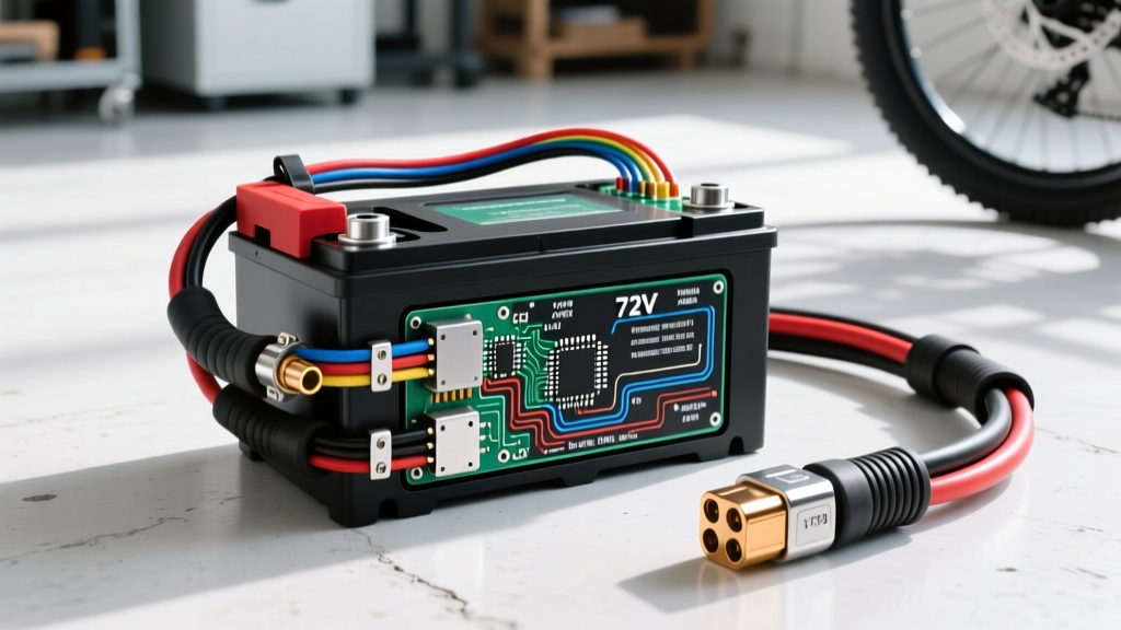
Why Automotive Power Distribution Standards Apply to 72V E-Bikes
When building or upgrading a high-performance 72V (20S) electric bike, you are no longer dealing with simple consumer electronics. A 72V system pushing 100+ amps to a brushless DC (BLDC) motor generates over 7,200 watts of continuous power. At this threshold, the electric bike battery wiring diagram must borrow heavily from automotive and marine power distribution standards. Standard PVC wire melts, undersized balance wires cause BMS failures, and poor soldering joints lead to catastrophic thermal runaway. As an automotive electrical specialist, I approach high-power e-bike builds using SAE (Society of Automotive Engineers) principles for high-current DC management, ensuring your battery management system (BMS), main discharge loops, and charge circuits are both safe and efficient.
Core Component Specifications and AWG Requirements
Before cutting any wire, you must select components capable of handling extreme DC current without excessive voltage drop. According to SAE J1284 standards for battery cables, high-strand-count silicone wire is mandatory for flexibility and heat resistance in high-vibration environments like bicycle frames.
| Circuit Function | Wire Type & AWG | Connector / Terminal | Max Continuous Current |
|---|---|---|---|
| Main Discharge (B- to P-) | 8 AWG Silicone (1050 Strands) | XT90-S (Anti-Spark) / 8mm Bullet | 120A - 150A |
| Main Charge Circuit (C-) | 12 AWG Silicone (680 Strands) | Anderson SB50 / XLR | 30A - 50A |
| BMS Sense Wires (B1-B20) | 22 AWG Stranded Tinned Copper | 21-Pin JST-SM Connector | 50mA (Balancing) |
| Main Battery Fuse | N/A (Inline on Positive Lead) | MIDI / AMEG Fuse Holder (150A) | 150A Blow Rating |
Step-by-Step: Executing the Electric Bike Battery Wiring Diagram
A proper 20S lithium-ion wiring diagram centers around the BMS. The BMS monitors individual cell group voltages, manages thermal thresholds, and acts as a solid-state relay for overcurrent protection. Below is the precise installation sequence.
Phase 1: 20S BMS Sense Wire Routing and Verification
The most common cause of BMS destruction during installation is plugging in the sense wire harness incorrectly. The 21-pin JST connector must be verified with a multimeter before it ever touches the BMS board.
- Solder the B- (Black) Wire: Solder the black 22 AWG wire to the main negative bus bar of your 20S battery pack. This is your ground reference.
- Sequential Cell Group Taps: Solder the subsequent wires (White, Yellow, Red alternating) to each positive nickel strip junction, moving sequentially from the lowest cell group (Group 1) up to Group 20.
- The Multimeter Verification Test: Set your DMM to DC Voltage. Place the black probe on the black wire pin of the JST connector. Place the red probe on pin 2 (first white wire). It should read ~3.0V to 4.2V. Move the red probe to pin 3. It should read ~6.0V to 8.4V (cumulative). Continue to pin 21, which should read your total pack voltage (e.g., 84.0V for a fully charged 20S pack).
- Connect to BMS: Only after confirming a perfectly sequential voltage ladder should you plug the JST connector into the BMS sense port.
Phase 2: Main Discharge, Charge Terminals, and MIDI Fusing
Automotive power distribution relies on proper fusing close to the power source. In an e-bike, the main positive lead must be protected by an inline MIDI fuse rated slightly above your controller's maximum continuous draw but below the wire's ampacity limit.
- B- (Battery Negative): Solder 8 AWG wire from the BMS B- pad directly to the main negative bus bar of the cell pack.
- P- (Discharge Negative): Solder 8 AWG wire from the BMS P- pad to the negative terminal of your XT90-S discharge connector. The XT90-S features a built-in 1kΩ anti-spark resistor to prevent damaging voltage spikes to your motor controller's capacitors upon connection.
- C- (Charge Negative): Solder 12 AWG wire from the BMS C- pad to your charge port. If your BMS does not have a dedicated C- pad, you must wire the charge port in parallel with the discharge port, but this disables separate charge/discharge current limiting.
- Main Positive (B+): The main positive bus bar of the battery pack wires directly to the XT90 positive terminal and the charge port positive terminal. The BMS only switches the negative side of the circuit. Install your 150A MIDI fuse on this main positive line, within 6 inches of the battery output.
High-Current Connector Termination: XT90 and Anderson SB50
Soldering high-current DC connectors requires proper thermal management. Using undersized irons results in 'cold joints' which increase electrical resistance, leading to localized heating and melted housings. Follow IPC-A-620 wire harness assembly standards for proper solder wetting and insulation management.
- Prep the Wire: Strip 8mm of insulation from your 8 AWG silicone wire. Twist the strands tightly and apply a light coat of rosin-core flux.
- Pre-Tin Both Surfaces: Using a 100W+ soldering station set to 380°C (715°F), pre-tin the copper wire and the brass XT90 terminal cup separately. Use 63/37 eutectic solder for a rapid liquid-to-solid transition.
- Join and Heat: Insert the pre-tinned wire into the terminal cup. Apply the iron to the outside of the brass cup until the solder flashes and flows smoothly into the joint. Hold still for 5 seconds to cool.
- Adhesive Heat Shrink: Slide 3:1 ratio dual-wall (adhesive-lined) heat shrink over the joint before soldering. Once cooled, apply heat until the adhesive purges slightly from the edges, creating a waterproof, vibration-proof seal compliant with marine ignition protection standards like SAE J1171.
Troubleshooting Decision Tree: BMS and Voltage Drop Faults
Even with a perfect electric bike battery wiring diagram, real-world variables can cause faults. Use this diagnostic tree to isolate issues:
Symptom: Motor Controller Cuts Out Under Heavy Load (Hill Climbs)
- Check 1: Measure voltage at the battery XT90 terminals under load. If voltage drops below 60V (Low Voltage Cutoff), proceed to Check 2.
- Check 2: Measure voltage directly at the cell pack bus bars under load. If bus bar voltage is high (e.g., 72V) but XT90 voltage is low (60V), you have a high-resistance fault. Inspect BMS P- solder joints and XT90 crimps for cold joints.
- Check 3: If bus bar voltage also drops to 60V, the BMS is likely undersized for the controller's peak amperage, or a cell group is severely unbalanced and triggering the BMS over-discharge protection.
Symptom: Battery Will Not Charge
- Check 1: Verify charger output voltage (should be 84.0V for a 20S pack).
- Check 2: Measure voltage at the charge port. If 0V, the charge fuse is blown or the BMS C- MOSFETs have tripped due to a previous over-current event during charging.
- Check 3: Disconnect the BMS sense harness and measure individual cell groups. If any group is below 2.5V, the BMS has entered 'sleep mode' or permanent lockout to prevent lithium plating. The pack must be manually jump-charged at the cell level (with extreme caution) to wake the BMS.
Authoritative References & Further Reading
Designing safe, high-current DC power distribution systems requires adherence to established engineering standards. The methodologies outlined in this guide are derived from the following resources:
- SAE J1284: Standard for Battery Cable design, ensuring proper strand count and insulation ratings for high-vibration, high-current DC applications.
- IPC-A-620: The global standard for cable and wire harness assemblies, dictating proper solder wetting, strain relief, and heat shrink application for automotive and aerospace environments.
- Battery University (Cadex Electronics): Comprehensive data on lithium-ion charging profiles, BMS balancing algorithms, and thermal runaway prevention.
By treating your e-bike build with the same rigor as an automotive EV powertrain, you ensure maximum power delivery, longevity, and safety on every ride.