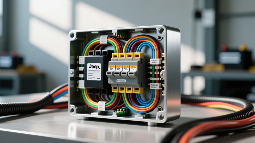
Why the Factory Fuse Box Wiring Diagram is Your Blueprint
When executing a complex auxiliary power modification—such as installing a multi-circuit auxiliary fuse block for off-road lighting, a winch solenoid, or a dual-battery management system—the factory Power Distribution Center (PDC) is your primary source for clean, switched, and constant 12V power. However, blindly probing wires with a test light is a guaranteed way to backfeed the Body Control Module (BCM) or melt a factory 16 AWG sense wire. To execute a professional-grade upgrade, you must learn to read and interpret the OEM fuse box wiring diagram. This schematic is the only reliable method for identifying true ignition-switched circuits, constant battery feeds, and CAN-bus lines that must be strictly avoided.
In modern vehicles like the 2018-2023 Jeep Wrangler JL, the electrical architecture is heavily multiplexed. The under-hood PDC contains high-current MEGA fuses, J-Case fuses, and standard Mini/ATO fuses. Understanding the specific pinouts, wire color codes, and amperage limits detailed in the factory service documentation ensures your aftermarket auxiliary fuse block integrates seamlessly without triggering parasitic draws or throwing U-codes (network communication faults).
Decoding the Jeep JL PDC Schematic
The factory service manual breaks the PDC down into distinct zones: the high-current B+ distribution zone (directly bolted to the battery positive terminal) and the switched logic zone (controlled by the TIPM or BCM). When reviewing the fuse box wiring diagram for an upfitter project, you are looking for circuits labeled as 'IG1' (Ignition 1 - Run/Start), 'ACC' (Accessory), or 'B+' (Battery Constant).
Below is a reference table for common Jeep JL PDC circuits utilized in aftermarket auxiliary power taps. Always verify with a multimeter against your specific model year, as mid-cycle manufacturing updates can alter wire color tracers.
| Circuit ID | Amperage | Wire Color (Mopar Code) | State | Recommended Mod Application |
|---|---|---|---|---|
| F92 (Aux PWR) | 20A | PK/WT (Pink/White) | Constant B+ | Dual Battery Isolator Logic / Memory Keep-Alive |
| F21 (IG1) | 15A | YL/VT (Yellow/Violet) | Ignition Run/Start | Aux Fuse Block Main Relay Coil Trigger |
| F45 (IOD) | 10A | RD/LG (Red/Light Green) | Ignition Off Draw | Low-Draw Telemetry / GPS Tracker |
| Main B+ Stud | 250A+ | N/A (Solid Copper Bus) | Constant B+ | High-Current Aux Block Feed (via MEGA Tap) |
The Danger of Standard Add-A-Circuits in High-Current Mods
A common and catastrophic mistake documented in off-road build forums is the use of standard ATM or APR 'Add-A-Circuit' (fuse tap) adapters to feed a 30A or 40A auxiliary fuse block. Standard fuse taps are manufactured with 18 AWG or 16 AWG lead wires, which are physically incapable of sustaining currents above 10A to 15A without severe voltage drop and thermal runaway. If you tap the F21 (15A) ignition circuit using a standard fuse tap to power a 40A auxiliary bus, the 16 AWG tap wire becomes the de-facto fuse. It will melt into the factory harness long before the 15A Mini-fuse blows, resulting in a localized electrical fire.
The Correct High-Current Tap Method
For auxiliary fuse blocks requiring 30A to 60A, you must bypass the low-amperage Mini-fuse grid entirely. According to Littelfuse automotive specifications, high-current distribution requires MEGA or ANL fuse profiles. The proper method involves installing a MEGA-fuse tap directly over the main B+ stud in the PDC, protected by a 60A or 80A MEGA fuse. You then route an 8 AWG or 6 AWG TXL primary wire from this tap to your auxiliary fuse block. The auxiliary block is then triggered by a heavy-duty 80A continuous-duty solenoid (such as a Blue Sea Systems ML-ACR), which is switched by the low-amperage F21 ignition circuit. This isolates the high-current load from the factory logic wiring.
Wire Selection, Routing, and Termination Standards
When running power from the PDC to a firewall-mounted or fender-mounted auxiliary fuse block, wire selection is critical. Do not use hardware store THHN wire; it lacks the chemical resistance to automotive fluids and the flexibility to withstand engine bay vibration. You must use SAE J1128 compliant TXL or GXL cross-linked polyethylene wire. TXL features a thinner insulation wall, allowing for tighter bend radii in crowded engine bays while maintaining high-temperature resistance up to 125°C.
Crimping and Connector Selection
For the auxiliary fuse block outputs, standard open-barrel crimps are unacceptable for exposed engine bay environments. Utilize sealed connector systems such as the Deutsch DT series or Molex MX150. These connectors feature silicone rear grommets and secondary locking wedges (TPA) that prevent moisture ingress and pin back-out. When crimping 8 AWG TXL wire to a 3/8-inch ring terminal for the main B+ feed, use a closed-barrel hex crimp die or an open-barrel F-crimp die specifically calibrated for 8 AWG, followed by a layer of 3M Scotchlok adhesive-lined heat shrink to seal the wire entry point against capillary corrosion.
Grounding the Auxiliary Block: Avoiding the 'Dirty Ground'
An auxiliary fuse block is only as reliable as its ground path. A frequent cause of flickering off-road lights and erratic relay chatter is a high-resistance ground. Never ground a high-current auxiliary block to a painted chassis surface or a thin sheet-metal bracket.
Locate a factory M8 or M10 ground stud on the frame rail or engine block. Remove the factory nut, clean the mating surface with a wire brush to bare, shiny metal, and apply a thin layer of NOALOX (anti-oxidant compound) to prevent galvanic corrosion. Stack your auxiliary ground ring terminal directly against the chassis, followed by the factory grounds, and torque the M8 nut to 18-22 Nm (13-16 lb-ft) or the M10 nut to 35 Nm (26 lb-ft) per Stellantis TechConnect service guidelines. Finally, coat the entire terminated stud in dielectric grease or liquid electrical tape.
Protecting the BCM from Inductive Flyback
When using the ignition-switched circuit (e.g., F21) to trigger the coils of multiple aftermarket relays housed in your auxiliary fuse block, you introduce a massive inductive load to the factory wiring. When a relay coil is de-energized, the collapsing magnetic field generates a high-voltage reverse spike (flyback voltage) that can exceed 100V. In older vehicles, this spike simply caused a spark across the switch contacts. In a modern Jeep JL, this spike travels back through the fuse box wiring harness and can instantly destroy the solid-state drivers inside the BCM.
To prevent this, every relay coil triggered by a factory logic circuit must be equipped with a flyback suppression diode. Wire a 1N4007 rectifier diode in parallel with the relay coil (pins 85 and 86), ensuring the diode's cathode (the silver stripe) faces the positive 12V trigger source. This creates a closed loop for the inductive spike to safely dissipate as heat within the coil, entirely protecting the factory PDC and BCM architecture. Alternatively, purchase premium automotive relays (like those from Hella or Bosch) that feature built-in internal suppression resistors or diodes.
Reference Resources and Further Reading
Executing a reliable auxiliary power upgrade requires adherence to established automotive electrical standards. The following resources are essential for verifying wire ampacity, transient voltage protection, and OEM schematic interpretation:
- SAE J1113 (Electromagnetic Compatibility): Critical for understanding how to route high-current auxiliary wires away from CAN-bus and sensor harnesses to prevent electromagnetic interference (EMI). Read more via SAE International.
- Stellantis / Mopar TechConnect: The official portal for downloading model-year-specific PDC schematics, ground distribution charts, and connector pin-out diagrams.
- Delphi Automotive Connection Systems: Manufacturer specifications for terminal crimp heights, pull-out force requirements, and sealed connector mating cycles.
By treating the factory fuse box wiring diagram as an engineering blueprint rather than a mere suggestion, you ensure your vehicle's electrical modifications remain safe, reliable, and fully integrated with the OEM power distribution network.