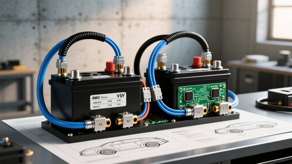
Introduction to Parallel 12V Architecture
When designing a dual-battery system for overland vehicles, marine applications, or heavy-duty diesel trucks, understanding the distinction between series and parallel circuits is critical. A series wiring configuration increases system voltage (e.g., two 12V batteries yield 24V), which will instantly destroy 12V ECUs, starters, and infotainment systems. Conversely, a parallel battery wiring diagram maintains the 12V nominal system voltage while mathematically summing the Amp-hour (Ah) capacity and Cold Cranking Amps (CCA) of the connected batteries. This advanced technical deep dive explores the precise topology, high-current cable management, and isolation logic required to build a reliable parallel 12V architecture using a Voltage Sensitive Relay (VSR) or Automatic Charging Relay (ACR).
The Physics of Parallel 12V Systems and Battery Matching
Before routing a single 1/0 AWG cable, an automotive electrical engineer must address internal resistance (IR) matching. When batteries are wired in parallel, they seek voltage equilibrium. If you parallel a brand-new Group 31 AGM battery with a three-year-old flooded lead-acid (FLA) battery, the newer battery (which has lower internal resistance and higher resting voltage) will continuously overcharge the older battery. This cross-charging leads to thermal runaway, excessive gassing, and accelerated sulfation. For any parallel battery wiring diagram to function safely, both the cranking and house batteries must share the exact same chemistry, age, and manufacturer specifications.
VSR vs. DC-DC: Selecting the Isolation Topology
Directly hardwiring two batteries in parallel without an isolation device means a parasitic draw on the house battery (e.g., a 12V compressor fridge) will eventually drain the cranking battery, leaving the vehicle stranded. To prevent this, we utilize isolation logic.
Voltage Sensitive Relay (VSR) Logic
A VSR, such as the Blue Sea 7610 ACR, monitors the voltage on both battery banks. When the alternator begins charging and system voltage rises to 13.7V for a set duration (typically 30 seconds), the internal coil energizes, closing a heavy-duty contactor that parallels the batteries. When the engine stops and voltage drops below 12.8V, the relay opens, isolating the house loads from the cranking battery. VSRs are ideal for identical lead-acid battery pairs.
DC-DC Charger Topology
If your parallel setup mixes chemistries (e.g., a lead-acid cranking battery and a LiFePO4 house battery), a VSR is dangerous. Lithium batteries have a near-flat voltage curve and extremely low internal resistance, which can cause the alternator's voltage regulator to misread system state, potentially overheating the alternator diodes. In mixed-chemistry parallel diagrams, a DC-DC charger (e.g., Victron Orion-Tr Smart) is mandatory to regulate the charging profile and provide galvanic isolation.
Advanced Parallel Battery Wiring Diagram: Step-by-Step Routing
Below is the technical breakdown of a high-current VSR parallel routing sequence, adhering to SAE J1128 low-tension primary cable standards and ABYC E-11 marine/overland DC guidelines.
- Cranking Battery to Fuse: Route a 1/0 AWG Red SAE J1128 cable from the positive terminal of Battery A (Cranking) to a 250A MEGA fuse holder. The fuse must be within 7 inches of the battery terminal to protect against dead-short fires.
- Fuse to VSR Stud A: Continue the 1/0 AWG Red cable from the load side of the MEGA fuse to Terminal Stud A on the VSR.
- VSR Stud B to House Fuse: Route a second 1/0 AWG Red cable from Terminal Stud B to a second 250A MEGA fuse, located within 7 inches of Battery B (House).
- House Fuse to House Battery: Complete the positive circuit to the positive terminal of Battery B.
- VSR Ground and Sense: Terminate the VSR ground wire (10 AWG Black) to a clean, bare-metal chassis ground. Connect the ignition sense wire (18 AWG Yellow/Red) to an ignition-switched 12V source to prevent the VSR from paralleling the batteries during solar charging or shore power events.
VSR / ACR Terminal Pinout Matrix
| Terminal / Pin | Wire Gauge | Color Code | Function & Torque Spec |
|---|---|---|---|
| Stud A (Input) | 1/0 AWG | Red | Cranking Battery Positive (12-15 ft-lbs) |
| Stud B (Output) | 1/0 AWG | Red | House Battery Positive (12-15 ft-lbs) |
| Pin 1 (Ground) | 10 AWG | Black | Chassis Ground / Battery Negative |
| Pin 2 (Sense) | 18 AWG | Yellow/Red | Ignition Sense / Manual Override |
High-Current Cable Sizing & Voltage Drop Calculations
Using undersized cables in a parallel battery wiring diagram causes severe voltage drop, which tricks the alternator's internal regulator into overcharging the system to compensate. According to Blue Sea Systems engineering documentation, voltage drop in critical charging circuits should not exceed 3%. The table below outlines the minimum AWG requirements for a 12V parallel interconnect carrying 200A, based on total cable length (positive + negative return).
| Total Circuit Length (ft) | Max Current (A) | Minimum AWG (3% Drop) | Recommended AWG (1% Drop) |
|---|---|---|---|
| 10 ft | 200A | 2 AWG | 1/0 AWG |
| 15 ft | 200A | 1/0 AWG | 2/0 AWG |
| 20 ft | 200A | 2/0 AWG | 4/0 AWG |
Always use pure copper, strand-count wire (e.g., Type III welding cable or SGG battery cable). Avoid Copper Clad Aluminum (CCA) wires found in budget kits, as they suffer from higher resistance, galvanic corrosion at the lugs, and poor flexibility in engine bay vibration zones.
Grounding Topology & The Big-3 Integration
A common catastrophic flaw in amateur parallel battery wiring diagrams is the grounding topology. If Battery A is grounded to the engine block, and Battery B is grounded to the rear chassis, the alternator's return current must travel through the entire vehicle chassis. The chassis steel acts as a high-resistance resistor, creating a voltage differential between the two battery negatives. This differential causes the batteries to 'fight' each other, resulting in localized heating and erratic ECU sensor readings.
To resolve this, integrate a 'Big-3' wiring upgrade. Run a dedicated 1/0 AWG Black ground cable directly from Battery A's negative terminal to Battery B's negative terminal, bypassing the chassis entirely for the high-current return path. Additionally, upgrade the alternator casing to chassis ground, and the engine block to chassis ground using 1/0 AWG cables. All ground lugs must be terminated with a hydraulic hex-die crimper and sealed with adhesive-lined dual-wall heat shrink to prevent moisture ingress and copper oxidation.
Real-World Failure Modes & Oscilloscope Diagnostics
Even with a perfect parallel battery wiring diagram, components degrade. Here is how to diagnose advanced failure modes using an automotive oscilloscope and a millivolt meter.
1. Alternator Ripple and VSR Chatter
If the alternator's diode trio begins to fail, it leaks excessive AC ripple current into the DC system. A VSR monitors DC voltage; however, heavy AC ripple can cause the VSR's internal logic board to rapidly cycle the contactor open and closed (chatter). This arcing will weld the internal contacts shut, permanently paralleling the batteries. Diagnostic Fix: Connect an oscilloscope to the battery positive. If AC ripple exceeds 300mV, replace the alternator diodes or install a 4700µF filtering capacitor across the VSR sense circuit.
2. Parasitic Draw via FET Failure
A healthy VSR draws roughly 10mA to 30mA when the coil is open. If the internal Field Effect Transistor (FET) shorts out, the coil may draw several amps continuously, draining the cranking battery over a week of inactivity. Diagnostic Fix: Perform a parasitic draw test using a shunt-style ammeter. If the draw exceeds 50mA with all vehicle modules asleep, disconnect the VSR ground wire. If the draw drops to normal, the VSR logic board has failed and requires replacement.
3. Lug Micro-Arcing and Voltage Drop
Improperly crimped lugs or loose terminal nuts create micro-arcing under high alternator output. This manifests as a localized voltage drop. Diagnostic Fix: With the engine running at 2000 RPM and heavy DC loads applied, use a digital multimeter set to DC millivolts. Place the red probe on the battery post and the black probe on the cable lug barrel. A reading above 10mV per connection indicates high resistance, requiring the lug to be cut off, the wire stripped, and a new hydraulic crimp applied. Always torque 3/8-inch stainless steel or silicon bronze terminal nuts to exactly 12-15 ft-lbs using a calibrated torque wrench, as referenced in Littelfuse MEGA fuse hardware specifications, to prevent thread galling and ensure optimal surface contact area.