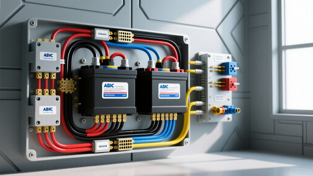
Engineering the Marine Dual Battery Architecture
Designing a robust marine electrical system requires a fundamental departure from standard automotive wiring practices. While a typical truck or SUV relies on SAE J1128 standards, a marine environment demands strict adherence to the American Boat & Yacht Council (ABYC) E-11 standards. When drafting a boat dual battery wiring diagram, the primary objective is to isolate the high-cranking-amperage demands of the engine from the deep-cycle requirements of the house bank (livewells, chartplotters, radios, and lighting). Failure to properly isolate these banks results in stranded vessels, parasitic drains, and catastrophic voltage drops.
One of the most critical distinctions in marine wiring is conductor selection. Unlike automotive wire, which typically uses untinned copper, marine environments require Type 3 stranded, tinned copper wire. The tin plating prevents galvanic corrosion and capillary wicking, which can turn a copper conductor into a brittle, high-resistance green oxide rod within a single season of saltwater exposure. Furthermore, ABYC color codes differ significantly from automotive conventions: DC Positive is typically Yellow (or Red for ungrounded systems), and DC Negative is Black or Yellow with a Black stripe. Always prioritize marine-grade color coding when mapping your schematic to avoid fatal polarity errors during maintenance.
Combiner Topologies: VSR vs. Diode Isolators
The core of any boat dual battery wiring diagram is the combiner mechanism that links the cranking and house banks during charging, yet separates them during discharge. There are two primary architectures utilized in modern 12V and 24V marine systems.
Voltage Sensitive Relays (VSR)
A VSR is an electromechanical relay that monitors the voltage of the primary (cranking) battery. When the alternator raises the cranking battery voltage to a predefined threshold (typically 13.7V for 12V systems), the VSR engages, paralleling the house bank to the charging source. When the engine is shut off and voltage drops below 12.8V, the VSR disconnects, isolating the banks. VSRs are highly efficient because they introduce near-zero voltage drop across the contacts. However, they require a dedicated ground wire (usually 10 AWG Black) and a small sense wire to monitor battery terminals directly, compensating for voltage drop in the main charging cables.
Solid-State Diode Isolators
Diode isolators use semiconductor junctions to direct alternator output to multiple battery banks without allowing current to flow backward between them. While they are solid-state and have no moving parts, they introduce a forward voltage drop of 0.7V to 1.2V. In a 12V system, a 1.0V drop means the house bank might only see 13.2V when the alternator is pushing 14.2V, resulting in chronic undercharging and sulfation. If you utilize a diode isolator in your boat dual battery wiring diagram, you must route an alternator sense wire directly to the house bank positive terminal to force the internal regulator to compensate for the diode drop.
Sizing the Conductors: AWG and Voltage Drop
Marine electrical systems are highly sensitive to voltage drop. ABYC recommends a maximum 3% voltage drop for critical navigation and communication circuits, and a maximum 10% drop for non-critical house loads. Sizing the main battery interconnect cables requires calculating the round-trip distance from the cranking battery positive, through the VSR, to the house bank positive, and back via the common ground bus.
| AWG Size | Stranding (Type 3) | Max Ampacity (Engine Space) | Resistance (Ohms/1000ft) | Typical Application |
|---|---|---|---|---|
| 4/0 AWG | 426 strands | 302 Amps | 0.0608 | Main Engine Cranking & Inverter Banks |
| 2/0 AWG | 266 strands | 239 Amps | 0.0766 | High-Output Alternator to Main Bus |
| 1/0 AWG | 210 strands | 190 Amps | 0.0967 | VSR Interconnects (Short Runs) |
| 2 AWG | 133 strands | 150 Amps | 0.1563 | Windlasses and Bow Thrusters |
| 4 AWG | 84 strands | 119 Amps | 0.2485 | House Bank to DC Distribution Panel |
To calculate the exact voltage drop for your specific boat dual battery wiring diagram, use the formula: VD = (2 x L x I x R) / 1000, where L is the one-way length in feet, I is the maximum expected current, and R is the resistance per 1000 feet of the chosen AWG.
Step-by-Step Execution and Fusing
- Install Common Negative Busbars: Mount a heavy-duty, tin-plated copper busbar in a dry location. Connect the negative terminals of both the cranking and house banks to this busbar using 2/0 AWG tinned cable. This ensures a common reference ground and prevents ground loops that can interfere with marine audio and VHF radios.
- Route Positive Cabling: Run 2/0 AWG Yellow (or Red) tinned marine wire from the cranking battery positive to a Marine Battery Fuse (MRBF) terminal fuse rated for the alternator's maximum output plus 20%. From the MRBF, route to the VSR common stud.
- Connect the VSR: Attach the VSR output stud to the house bank positive via a secondary MRBF or Class T fuse. The Class T fuse is critical for lithium (LiFePO4) house banks due to their massive short-circuit current potential, which can exceed the interrupt rating of standard ANL fuses.
- Wire the VSR Sense and Ground: Run a 10 AWG Black wire from the VSR negative terminal to the common ground bus. Run a 10 AWG Yellow sense wire directly to the cranking battery positive terminal to ensure the VSR reads true terminal voltage, not alternator output voltage degraded by cable resistance.
Termination and Environmental Sealing
The most common point of failure in any marine wiring diagram is the terminal lug. Do not use standard automotive indent crimpers. Marine standards require a hex-crimp die that compresses the copper strands into a solid, uniform hexagonal shape, eliminating air pockets where moisture can accumulate. After crimping, you must seal the termination using adhesive-lined polyolefin heat shrink. When heated, the inner thermoplastic adhesive melts and flows into the wire strands, creating a watertight seal that prevents capillary action. Finally, torque all terminal nuts to the manufacturer's specification (typically 10-12 ft-lbs for 3/8-inch studs) using a calibrated torque wrench, and coat the exposed copper with a dielectric grease or specialized marine terminal spray.
Diagnostic Troubleshooting Matrix
- Symptom: House bank fails to charge, but alternator output is verified at 14.2V.
Cause: VSR sense wire is reading voltage drop, or VSR internal coil is open.
Fix: Measure voltage directly at the VSR sense terminal. If below 13.7V, repair the sense wire. If 13.7V+ and VSR does not click, replace the VSR. - Symptom: Cranking battery drains overnight alongside the house bank.
Cause: VSR contacts are welded shut due to high-inrush current from a house inverter.
Fix: Replace the VSR with a higher-rated unit (e.g., 500A continuous) and ensure the inverter is wired to a dedicated battery bank, not through the VSR. - Symptom: VHF Radio squelch breaks when livewell pump activates.
Cause: Voltage drop on the DC distribution bus exceeding 3%, or improper negative return routing.
Fix: Upgrade distribution wiring to 4 AWG and verify the negative busbar connection is free of oxidation and torqued correctly.
For comprehensive regulatory guidelines, always consult the ABYC E-11 AC & DC Electrical Systems documentation. For component-specific circuit topologies and interrupt ratings, reference the Blue Sea Systems Circuit Protection Library. When integrating advanced battery chemistries or high-output alternators, Mastervolt Technical Support provides excellent schematics for digital battery combiners and BMS integration.