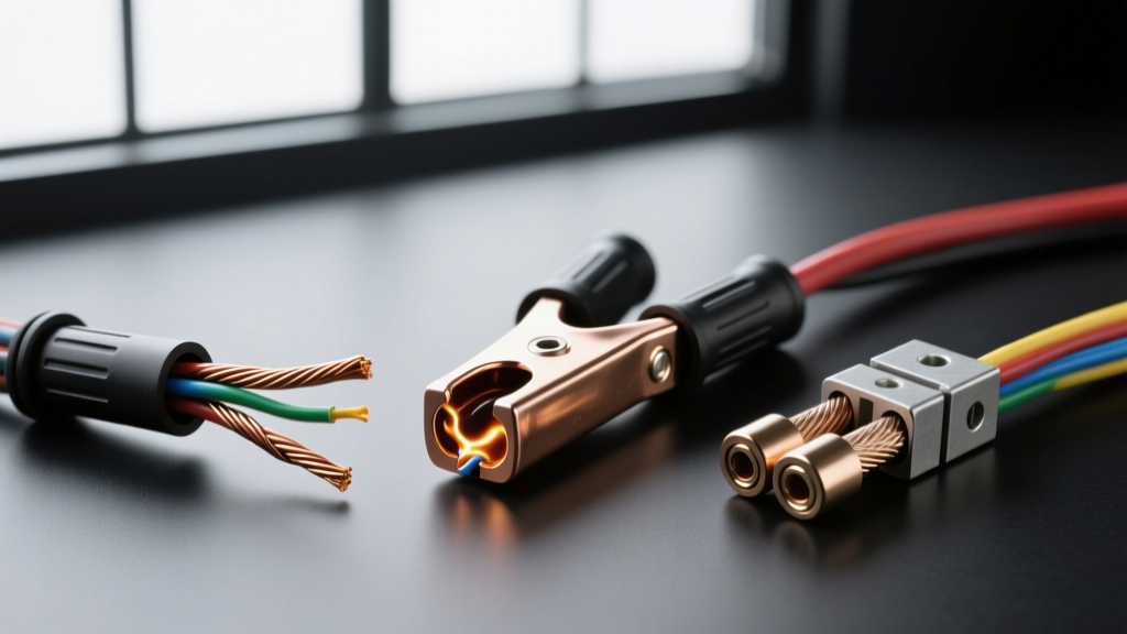
The Critical Role of Ground Wire Splicing in 12V Systems
In automotive and marine electrical systems, the ground circuit carries the exact same current as the positive supply. When you need to extend a harness, repair a damaged chassis ground, or add a secondary return path, the method you choose to splice ground wire connections dictates the long-term reliability of the entire circuit. A poor ground splice introduces resistance, leading to voltage drops, erratic sensor behavior, and in high-current applications, dangerous thermal runaway.
According to SAE International guidelines for low-tension primary cable, grounding circuits must maintain a near-zero millivolt drop under peak load. This guide compares the three primary methods to splice ground wire setups—heat-shrink butt crimps, solder seal sleeves, and bus bar distribution—to help you select the right termination for your specific AWG and environmental requirements.
Method 1: Polyolefin Heat-Shrink Butt Crimps (The Industry Standard)
The most reliable inline method to splice ground wire connections in high-vibration environments is the polyolefin heat-shrink butt crimp. Unlike standard vinyl or nylon insulated crimps, marine-grade polyolefin connectors feature an inner layer of hot-melt adhesive that melts during the shrinking process, creating a waterproof, gas-tight seal around the copper strands.
Technical Specifications & Best Practices
- Material: Tin-plated copper barrel to prevent galvanic corrosion when mating with standard copper wire (Black for SAE DC ground, White for marine ground).
- Tooling: Requires a dedicated ratchet crimper (e.g., IWISS IWS-16 or Ancor Marine Crimp Tool) with the correct die size. For 12-10 AWG wire, use the yellow die (1.5-2.5mm²).
- Shrink Temperature: Polyolefin tubing requires approximately 125°C (257°F) to shrink properly. A dedicated heat gun is mandatory; open flames or lighters will scorch the tubing and destroy the adhesive seal.
- Pull-Out Force: When properly crimped, a 10 AWG heat-shrink butt splice exceeds the UL 486A standard of 120 lbs of tensile pull-out force.
Pros and Cons
Pros: Exceptional vibration resistance; the cold-weld created by a proper ratchet crimp prevents the copper strands from loosening over time. The adhesive seal blocks moisture and halts capillary-action corrosion.
Cons: Requires expensive, specialized ratchet tooling. If the crimper is out of calibration, the barrel may be under-compressed (leading to high resistance) or over-compressed (severing strands).
Method 2: Solder Seal Splice Connectors
Solder sleeves utilize a ring of low-temperature solder in the center of a heat-shrink tube. When heated, the solder melts and flows around the stripped wire ends to fuse them together. While popular in quick-fix kits, using solder to splice ground wire connections in high-current automotive applications is highly debated among electrical engineers.
The Vibration and Thermal Cycling Problem
Solder is a rigid, brittle metal. In an engine bay or chassis environment subject to constant harmonic vibration and extreme thermal cycling (from -20°F to 250°F+), the rigid solder joint acts as a stress concentrator. The copper wire immediately adjacent to the solder blob work-hardens and eventually fractures. Furthermore, solder has a higher electrical resistance than copper. In a 10 AWG ground wire carrying 30 amps, a solder joint will run hotter than the surrounding wire, accelerating thermal degradation.
While acceptable for low-current sensor grounds (18-22 AWG) inside the cabin, solder sleeves should never be used to splice ground wire connections for high-current loads like starter motors, winches, or high-amperage alternator returns.
Method 3: Terminal Block / Bus Bar Distribution (The Superior Alternative)
The absolute best practice in modern automotive power distribution is to avoid inline splices entirely. Instead of cutting and splicing a ground wire, route the primary ground to a centralized, tin-plated copper bus bar, and use individual ring terminals for each branch circuit. Blue Sea Systems heavily advocates for this star-point grounding topology to eliminate ground loops and simplify troubleshooting.
Hardware and Torque Specifications
When terminating to a bus bar rather than using an inline splice, you must adhere to strict mechanical torque specifications to ensure a gas-tight connection. For a standard 1/4"-20 UNC stainless steel bolt on a tin-plated copper busbar, the target torque is 75 to 120 in-lbs. Under-torquing allows micro-movements that cause fretting corrosion; over-torquing strips the threads or deforms the ring terminal, reducing the surface contact area and increasing resistance.
Technical Comparison Chart: Splice Ground Wire Methods
| Method | Tensile Strength | Vibration Resistance | Moisture IP Rating | Best Use Case |
|---|---|---|---|---|
| Polyolefin Butt Crimp | High (120+ lbs) | Excellent | IP67 (Submersible) | Inline harness repair, chassis extensions (10-8 AWG) |
| Solder Seal Sleeve | Low (30-50 lbs) | Poor (Brittle) | IP65 (Splashes) | Low-current cabin sensors, static wire extensions (18-22 AWG) |
| Bus Bar Ring Terminals | N/A (Bolted) | Excellent | Depends on enclosure | Centralized grounding, high-current returns (4-1/0 AWG) |
| Nylon/Vinyl Crimp | Medium (80 lbs) | Good | IP20 (Indoor only) | Temporary fixes, dry interior cabin splices only |
Step-by-Step: Executing the Perfect 10 AWG Ground Splice
If your application dictates that you must inline splice a 10 AWG black ground wire, follow this exact procedure to guarantee a zero-failure termination. This methodology aligns with Ancor Products marine-grade termination standards.
- Strip the Wire Precisely: Use a calibrated wire stripper to remove exactly 5/16" (8mm) of insulation. Do not nick the copper strands. Nicks create weak points that will snap under vibration.
- Pre-Insert and Check: Insert the stripped wire into the metal barrel of the heat-shrink butt connector. The copper strands should be flush with the end of the barrel—no bare copper should be visible outside the metal sleeve, and no insulation should be crimped inside the barrel.
- Perform the Crimp: Place the connector in the yellow (12-10 AWG) die of your ratchet crimper. Ensure the seam of the butt connector is facing the flat side of the die, not the indentor. Squeeze the ratchet until it releases. This ensures a consistent, calibrated compression that cold-welds the copper strands to the tin-plated barrel.
- Apply Heat: Using a heat gun set to roughly 300°C, apply heat evenly starting from the center of the connector and moving outward toward the wire insulation. Stop heating the moment the hot-melt adhesive squeezes out of both ends. This visual indicator confirms a watertight seal.
- Let it Cool Naturally: Do not quench the connector in water or blow on it. Let it cool naturally to allow the adhesive to set properly around the wire jacket.
Common Failure Modes & Troubleshooting Ground Splices
Even with premium materials, ground splices can fail if environmental factors are ignored. Here are the most common failure modes and how to diagnose them.
Galvanic Corrosion
If you use a standard copper butt crimp to splice a ground wire that connects to an aluminum chassis or engine block, you create a galvanic cell. In the presence of moisture, the aluminum will act as a sacrificial anode and corrode rapidly, destroying the ground path. The Fix: Always use dielectric grease on the chassis attachment point, and utilize star washers to bite through paint and anodized layers to reach bare metal.
Cold Crimps (High Resistance)
A 'cold crimp' occurs when the crimping tool lacks sufficient mechanical advantage to deform the copper barrel into the wire strands. This leaves microscopic air gaps that increase electrical resistance. The Diagnosis: Perform a voltage drop test. Set your multimeter to DC Volts. Place the positive probe on the battery negative terminal and the negative probe on the component's ground housing. Run the circuit under load. A reading above 0.10V indicates excessive resistance in the ground path, likely pointing to a failing splice or corroded ring terminal.
Thermal Degradation of Insulation
Routing a spliced ground wire too close to exhaust manifolds or turbochargers will melt the polyolefin shrink tubing, exposing the copper to moisture and debris. Always use high-temperature fiberglass sleeving or corrugated loom with high-temp tape when routing ground splices within 12 inches of exhaust components.
Final Verdict: Which Method Should You Choose?
When deciding how to splice ground wire connections in your vehicle, the choice comes down to current load and environment. For inline repairs on 18 AWG to 8 AWG wires, polyolefin heat-shrink butt crimps executed with a ratchet tool are the undisputed champion, offering superior vibration resistance and moisture sealing. Avoid solder sleeves for anything carrying more than 5 amps. Finally, for new builds or major electrical overhauls, abandon inline splices altogether and route your ground wires to a centralized tin-plated bus bar for the ultimate in reliability and serviceability.