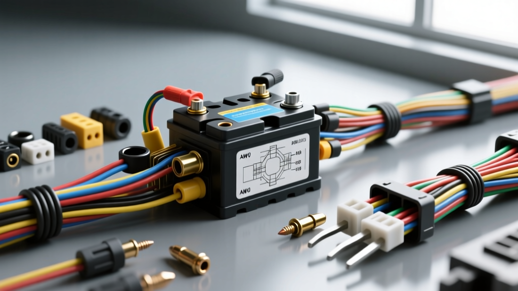
Introduction: Reading the Power Distribution Schematic
Every automotive electrical schematic begins at a single, critical point of origin: the battery terminal. In OEM wiring diagrams, this is designated as Node 0, the primary B+ (positive) and B- (negative) distribution hub. Understanding the physical and electrical characteristics of car battery terminal connector types is essential for tracing power flow, performing Big-3 wiring upgrades, and diagnosing parasitic draws or cranking voltage drops. When you read a factory service manual wiring diagram, the terminal connector is not just a mechanical clamp; it is the primary transitional node between the electrochemical cell and the vehicle's copper distribution network. This walkthrough will trace the power distribution schematic from the battery post interface through the main feeds, highlighting connector specifications, AWG requirements, and real-world failure modes.
Node 1: The Battery Post Interface (SAE & BCI Standards)
The physical connection at the battery is governed by strict dimensional standards to ensure compatibility and prevent reverse polarity. The two most common car battery terminal connector types found in North American and global markets are the Top Post (Tapered) and the Side Post (Threaded).
Top Post Terminals (SAE J563 Standard)
The standard top post terminal follows the SAE J563 specification, maintained in conjunction with the Battery Council International (BCI). The positive post measures 17.5mm in diameter at the base, tapering to 15.9mm at the top. The negative post is smaller, measuring 15.9mm at the base and 14.3mm at the top. This deliberate asymmetry is a physical fail-safe against reverse polarity installation.
- Standard Lead-Acid Clamps: Typically cast from lead-antimony alloy or stamped from copper-brass alloys. They rely on radial compression to establish a low-resistance gas-tight seal with the lead post.
- Military / Dual-Stud Adapters: Frequently used in off-road and dual-battery setups. These clamp onto the SAE tapered post but provide two 3/8" threaded studs on top. This allows the integration of multiple ring terminals (e.g., a 1/0 AWG main feed and a 4 AWG auxiliary winch feed) without stacking lugs dangerously under a single bolt.
- Shim Usage: When dealing with undersized or corroded lead posts, copper or stainless steel shims are used to increase the clamping diameter. Never use aluminum shims, as galvanic corrosion between aluminum, copper, and lead will rapidly destroy the connection.
Side Post Terminals (GM Specifics & Torque Limits)
General Motors utilized side post terminals extensively from the 1970s through the early 2010s. The wiring diagrams for these vehicles show the main power and ground cables routing directly into the side of the battery case. The connector features a 3/8-16 UNC internal threaded insert cast into the lead post.
Critical Installation Note: The threaded insert is encapsulated in relatively soft lead. Overtorquing the terminal bolt will strip the insert or crack the battery case, leading to acid weeping. The factory service manual torque specification for GM side post terminals is strictly 11 to 15 Nm (8 to 11 lb-ft). Furthermore, the wiring diagram often depicts a specialized "spacer" or "shim" washer between the cable lug and the battery case to prevent the terminal bolt from bottoming out and cracking the internal lead connection.
Node 2: Main Power Feed Routing & AWG Selection
Once the power passes through the terminal connector, the wiring diagram splits the main B+ feed into two primary branches: the Starter Motor feed and the Underhood Bussed Electrical Center (UBEC) feed. The AWG (American Wire Gauge) size of the cable lugs crimped to these terminals must match the current demands of the vehicle.
| Connector Type | Post Standard | Max Recommended AWG | Torque Spec (Nm) | Primary Application |
|---|---|---|---|---|
| Standard Top Post Clamp | SAE J563 Taper | 1/0 AWG to 2/0 AWG | 9 - 12 Nm | Global OEM Standard |
| GM Side Post Lug | 3/8-16 UNC Thread | 2 AWG to 1/0 AWG | 11 - 15 Nm | GM Vehicles (1970-2010) |
| Military / Dual-Stud | SAE Base + 3/8 Studs | Multiple Ring Terms | 7 - 9 Nm (Studs) | Off-Road / Auxiliary Bus |
| Marine Wingnut | 3/8-16 Stud | 4 AWG (Max) | Hand Tight | Light Marine (Avoid Auto) |
For modern V8 engines requiring 200+ amps of cranking current, OEM wiring diagrams specify 1/0 AWG (0 AWG) or 2/0 AWG pure copper (OFHC) cables. When performing a Big-3 wiring upgrade, enthusiasts often upgrade the terminal connectors to heavy-duty brass or tinned-copper clamps to accommodate 1/0 AWG lugs, ensuring the terminal itself does not become a bottleneck in the high-current schematic.
Node 3: Secondary Distribution & Fusible Links
Tracing the schematic further from the positive terminal, you will encounter the primary overcurrent protection. In older wiring diagrams (1980s-1990s), this takes the form of a Fusible Link—a specialized wire gauge sized four steps smaller than the main feed (e.g., a 10 AWG fusible link protecting a 6 AWG main feed), wrapped in high-temperature Hypalon insulation.
In modern diagrams (2000-present), the B+ terminal connector often integrates directly into a Mega Fuse (150A - 250A) or an ANL Fuse holder mounted directly adjacent to the battery. The ground side (B-) schematic is equally critical. The main ground cable (typically Black, 1/0 AWG) routes from the negative terminal to the engine block, establishing the primary reference ground for the ECU, alternator, and starter. Secondary ground straps (typically 4 AWG or 6 AWG braided copper) then bridge the engine block to the chassis, and the chassis to the unibody, completing the return path to the battery terminal.
Troubleshooting Voltage Drop at the Terminal Node
When diagnosing starting issues, parasitic draws, or erratic sensor behavior, the wiring diagram dictates that you must verify the integrity of Node 0 before testing downstream components. A failing terminal connector acts as a resistor, generating heat and causing voltage drops.
Real-World Failure Modes & Diagram Tracing
- Galvanic Corrosion (Copper Sulfate): When the protective seal of the terminal clamp fails, battery acid vapors react with the copper strands inside the cable jacket. This creates a blue/white crystalline powder (copper sulfate). Copper sulfate is a semiconductor; it allows low-amperage parasitic currents to pass but chokes under high-amperage cranking loads. Fix: Cut back the cable to clean OFHC copper, replace the terminal clamp, and apply a dielectric grease or specialized battery terminal spray.
- ECM Brownout Codes (e.g., U0100): If the terminal connector is loose, the massive current draw of the starter motor (often 250A+) causes the system voltage at the UBEC to drop below 9.0V. Modern Engine Control Modules (ECMs) will reset or throw CAN-bus communication codes during crank. Tracing the diagram to the ECM power relay feed confirms that the relay is starved of voltage due to terminal resistance.
- The Voltage Drop Test: Using a digital multimeter, place the positive probe directly on the bare lead battery post (Test Point 1) and the negative probe on the copper cable lug crimped inside the terminal clamp (Test Point 2). Have an assistant crank the engine. According to established automotive diagnostic protocols, the voltage drop across the terminal interface must not exceed 0.1V (100mV) under full cranking load. A reading of 0.3V or higher indicates a failed mechanical clamp or internal cable oxidation.
Conclusion: Securing the Primary Power Node
A vehicle's electrical architecture is only as robust as its primary connection point. Whether you are restoring a classic car with standard SAE J563 top post clamps, maintaining a GM fleet with side post lugs, or fabricating a custom dual-battery setup with military-style adapters, respecting the torque specifications, AWG limits, and environmental sealing requirements is non-negotiable. By treating the battery terminal not just as a hardware attachment, but as the foundational node of your entire wiring diagram, you ensure reliable power distribution, accurate sensor referencing, and long-term electrical stability. Always consult the specific BCI terminal standards and OEM service manuals when selecting replacement connectors for your power distribution system.