Why Factory Battery Terminals Fail in Modified Vehicles
When upgrading a vehicle for high-current applications—such as massive car audio systems, off-road winching, or full EV conversions—the factory electrical system quickly becomes a bottleneck. Original equipment manufacturer (OEM) battery clamps are typically cast from lead or a lead-antimony alloy. While adequate for a stock 80-amp alternator and standard vehicle electronics, lead is a notoriously poor conductor compared to copper and is highly susceptible to mechanical creep and galvanic corrosion.
When you push 250+ amps through a Big 3 wiring upgrade, factory clamps can overheat, deform, and lose clamping force over time due to engine bay heat cycles. This increased resistance leads to voltage drop, alternator whine in audio systems, and sluggish cranking speeds. Upgrading to heavy-duty car battery cable connectors is the critical first step in establishing a reliable, low-resistance foundation for any high-amperage modification project.
Selecting the Right Car Battery Cable Connectors for High-Amp Loads
Not all terminals are created equal. The transition from the battery post to the copper cable must be seamless, mechanically robust, and chemically stable. When sourcing car battery cable connectors for a modification project, you must evaluate both the material composition and the terminal geometry.
Material Science: Tinned Copper vs. Brass vs. Lead
- Lead-Antimony (OEM): High resistance, prone to cold flow (creep) under bolt pressure, and creates a galvanic cell when in direct contact with bare copper, resulting in destructive green corrosion.
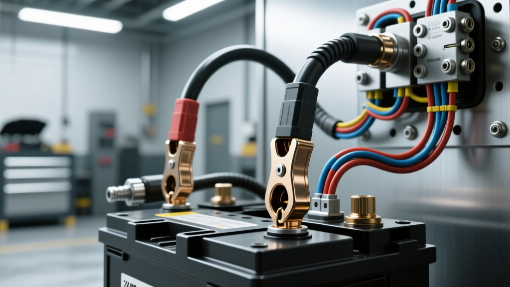
- Solid Brass/Bronze: Excellent mechanical strength and good conductivity. Often used in Military Specification (Mil-Spec) clamps. Brass does not deform under high torque, ensuring a permanent clamp.
- Tinned Oxygen-Free Copper (OFC): The gold standard for high-current ring terminals and busbar adapters. The tin plating prevents copper oxidation while maintaining near-perfect conductivity.
For any high-current build, avoid Copper-Clad Aluminum (CCA) cables and connectors. According to SAE J1128 standards regarding low-tension primary cable and general conductivity principles, CCA wire has a higher resistance than pure OFC copper and is prone to snapping under the heavy crimping pressures required for large-gauge battery terminals.
Terminal Styles: Mil-Spec vs. Standard Ring
For the actual battery post connection, Military Specification (Mil-Spec) battery clamps are the preferred choice for modified vehicles. Unlike top-post lead clamps that rely on wedge friction, Mil-Spec clamps utilize a brass saddle and a nut-and-bolt configuration. This allows you to securely clamp multiple heavy-gauge wires (e.g., a 1/0 AWG alternator charge wire and a 1/0 AWG main power distribution cable) directly to the battery post without the risk of the wires slipping or splaying under load.
Step-by-Step: Fabricating and Installing 1/0 AWG Upgraded Cables
Building custom battery cables requires precision. A poorly crimped connector will introduce more resistance than the wire itself, turning your expensive upgrade into a fire hazard.
Step 1: Stripping the Cable Without Scoring
When working with 1/0 AWG or 2/0 AWG OFC welding cable, use a specialized rotary cable stripper or a very careful touch with a razor knife. Never use standard wire strippers that bite into the copper strands. Scoring even a few strands reduces the cross-sectional area of the wire, creating a localized hot-spot that will melt the heat shrink and degrade the connection over time.
Step 2: Hex-Crimping for Uniform Radial Pressure
Avoid hammer-crimpers at all costs. Hammer crimps create voids inside the terminal barrel where moisture can pool, leading to internal capillary corrosion. Instead, use a hydraulic hex-crimping tool. A hex crimp applies uniform radial pressure, forcing the copper terminal barrel and the wire strands into a solid, homogeneous mass. This cold-welds the connection, achieving a pull-out strength that often exceeds the tensile strength of the wire itself.
Step 3: Sealing with Adhesive-Lined Heat Shrink
After crimping, seal the barrel with 3:1 adhesive-lined polyolefin heat shrink. Standard PVC heat shrink is insufficient for under-hood environments. When heated, the inner wall of adhesive-lined shrink melts and flows into the copper strands, creating a completely waterproof, airtight seal. This prevents the dreaded 'green crust' (copper sulfate) from forming inside the connector barrel, a common failure point noted by the Battery Council International (BCI) in their terminal maintenance guidelines.
Car Battery Cable Connector Specification & Torque Matrix
Proper torque is critical. Over-torquing can strip the threads on brass Mil-Spec clamps or crack battery casings, while under-torquing leaves micro-gaps that cause arcing and heat. Always use a calibrated inch-pound or low-range Newton-meter torque wrench.
| Connector Type | Best Application | Wire Gauge | Hardware Size | Torque Spec (Nm / lb-in) |
|---|---|---|---|---|
| Mil-Spec Top Post Clamp | Main Battery to Chassis/Alt | 1/0 to 2/0 AWG | 5/16' or M8 Bolt | 15-20 Nm / 130-175 lb-in |
| Copper Ring Terminal (M8) | Busbar / Fuse Block Ground | 1/0 to 4 AWG | M8 (5/16') Stud | 12-15 Nm / 105-130 lb-in |
| Copper Ring Terminal (M10) | Engine Block / Starter Stud | 1/0 to 2/0 AWG | M10 (3/8') Stud | 20-25 Nm / 175-220 lb-in |
| ANL Fuse Holder Terminal | Inline Main Power Protection | 1/0 to 1/4 AWG | M8 (5/16') Bolt | 12-15 Nm / 105-130 lb-in |
Note: Always apply a thin layer of dielectric grease or a dedicated battery terminal anti-corrosion spray (like No-Ox-Id) to the mating surfaces after torquing to prevent environmental oxidation.
Routing, Looming, and Grounding Best Practices
Upgrading your car battery cable connectors is only half the battle; how you route the cables dictates the longevity of the system. High-current 1/0 AWG cables are heavy and stiff. If left unsupported, engine vibration will transfer directly to the battery posts, eventually cracking the battery casing or loosening the terminal.
Vibration Isolation and Looming
Use split-loom tubing or high-temp Tesa cloth tape to protect the cables from abrasion against the chassis or firewall. Secure the cables every 6 to 8 inches using UV-resistant nylon zip ties or aluminum P-clamps with rubber cushions. When passing through the firewall, always use a rubber grommet and apply a dab of silicone sealant to prevent exhaust fumes and moisture from entering the cabin.
The Importance of the Big 3 Grounds
A high-current positive connection is useless without an equally robust return path. The 'Big 3' upgrade includes:
- Alternator Positive to Battery Positive: Ensures the alternator senses true battery voltage and charges at maximum output.
- Engine Block to Chassis: Provides a clean ground path for the starter motor and ignition system.
- Battery Negative to Chassis: Completes the main circuit for all vehicle accessories.
When terminating the ground side to the chassis, do not simply bolt a ring terminal over factory paint or powder coating. Use a wire wheel or sanding disc to remove the coating down to bare, shiny metal. Apply anti-corrosion compound over the bare metal, torque the terminal, and then cover the entire connection with liquid electrical tape or enamel paint to seal out moisture.
Troubleshooting Voltage Drop at the Terminal
Even with premium Mil-Spec car battery cable connectors, installation errors can cause resistance. The most accurate way to test a connection is not by measuring static voltage, but by performing a Voltage Drop Test under load.
How to Perform a Dynamic Voltage Drop Test
- Set your digital multimeter to the DC Millivolt (mV) scale.
- Place the red probe directly on the battery's lead post (not on the connector).
- Place the black probe on the copper wire, just past the heat shrink of the connector.
- Introduce a heavy electrical load. Have an assistant crank the engine, or turn on the headlights, rear defroster, and cooling fans simultaneously.
- Read the multimeter. A healthy, properly crimped and torqued connection should show a voltage drop of less than 10 mV (0.010V) per connection.
If your multimeter reads 50 mV or higher, you have a high-resistance connection. This is typically caused by an under-crimped terminal, a scored wire strand, or insufficient torque allowing micro-arcing. Disconnect the battery, disassemble the terminal, inspect for heat discoloration (a bluish tint on the brass indicates severe overheating), and rebuild the cable if necessary.
Conclusion
Upgrading to heavy-duty, properly crimped, and accurately torqued battery connectors is the bedrock of any successful automotive electrical modification. By abandoning factory lead clamps in favor of Mil-Spec brass and tinned copper ring terminals, and by adhering to strict fabrication standards like hex-crimping and adhesive heat-shrinking, you ensure that your high-output alternator and power-hungry accessories receive the clean, unrestricted current they require. Always respect the torque specifications and validate your work with dynamic voltage drop testing to guarantee a reliable, fire-safe electrical system for years to come.