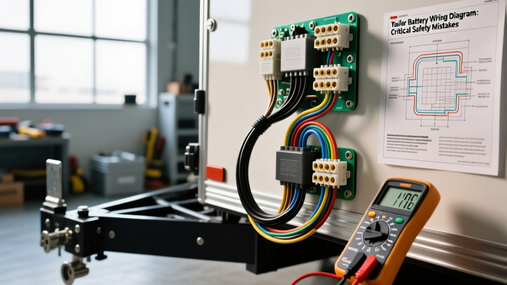
The Danger of Generic Trailer Battery Wiring Diagrams
When sourcing a trailer battery wiring diagram for a breakaway system, heavy-duty winch, or RV house bank, many DIYers rely on unverified forum sketches or generic search engine images. In high-current 12V DC environments, a misunderstood wiring schematic does not just result in a blown fuse—it can lead to melted harnesses, alternator destruction, or complete trailer brake failure during a detachment event. According to SAE J286 standards for trailer wiring, improper gauge sizing and incorrect pinout assignments are the leading causes of electrical fires in towable rigs.
As an automotive electrical specialist, I have audited hundreds of trailer setups. Below are the five most dangerous mistakes found in DIY trailer battery wiring diagrams, complete with the correct specifications, wire color codes, and safety protocols to ensure your rig is road-legal and fire-safe.
Mistake #1: Misinterpreting the 7-Way RV Blade Pinout
The most common point of failure occurs at the 7-way RV blade connector. Many generic diagrams fail to differentiate between the tail light ground and the dedicated battery charge line. Swapping these or overloading the auxiliary pin will fry your tow vehicle’s lighting control module or melt the connector housing.
SAE J286 Standard 7-Way Pinout Reference
| Pin Position | Function | Standard Wire Color | Max Safe Continuous Load |
|---|---|---|---|
| Pin 1 (Ground) | White - Main System Ground | White (10 AWG min) | 40A (Total System Return) |
| Pin 2 (Tail/Running) | Brown - Marker & Tail Lights | Brown (16 AWG) | 7.5A |
| Pin 3 (Left Turn/Stop) | Red - Left Turn & Stop | Red (14 AWG) | 10A |
| Pin 4 (12V Aux/Battery) | Black - 12V Battery Charge Feed | Black (10 AWG to 8 AWG) | 30A - 40A |
| Pin 5 (Right Turn/Stop) | Green - Right Turn & Stop | Green (14 AWG) | 10A |
| Pin 6 (Electric Brakes) | Blue - Brake Controller Output | Blue (12 AWG to 10 AWG) | 20A - 30A |
| Pin 7 (Aux/Reverse) | Yellow - Aux / Reverse Lockout | Yellow (14 AWG) | 10A |
The Safety Fix: Never use the Pin 4 (Black) 12V auxiliary feed to directly power a high-draw trailer winch. Pin 4 is designed for maintaining a breakaway battery or providing low-amperage house power. If your diagram shows a winch wired directly to the 7-way plug, discard it immediately. Winches require a dedicated onboard battery and heavy-gauge local wiring.
Mistake #2: Undersizing Wire Gauge for Breakaway Systems
A trailer breakaway system must apply maximum voltage to the electric brake magnets simultaneously if the trailer separates from the hitch. A standard 12-inch electric brake magnet draws roughly 3.0 to 3.5 amps. On a triple-axle trailer with six brakes, the instantaneous surge current can exceed 20 amps. Many flawed diagrams suggest using 14 AWG wire for the breakaway battery feed, which introduces severe voltage drop and weak braking force.
Voltage Drop Chart: 12V Breakaway System (20A Load)
| Wire Gauge (AWG) | Total Circuit Length (Pos + Neg) | Voltage Drop | Resulting Brake Voltage |
|---|---|---|---|
| 14 AWG | 20 Feet | 2.04V | 9.96V (Dangerous / Weak Braking) |
| 12 AWG | 20 Feet | 1.28V | 10.72V (Marginal) |
| 10 AWG | 20 Feet | 0.80V | 11.20V (Safe & Compliant) |
| 8 AWG | 20 Feet | 0.50V | 11.50V (Optimal Performance) |
The Safety Fix: Always use a minimum of 10 AWG SAE J1128 Type 3 (GXL/TXL) stranded copper wire for the main feed from the breakaway battery to the brake circuit junction. For trailers over 25 feet in length, upgrade to 8 AWG to ensure the magnets receive a full 12V during a catastrophic detachment.
Mistake #3: The 'Frame Ground' Myth
Countless outdated diagrams instruct builders to 'ground the battery negative to the trailer frame.' In modern trailers, this is a massive safety hazard. Many trailers utilize aluminum frames, painted steel, or pivot points (like torsion axle mounts) that interrupt electrical continuity. Relying on the frame for high-current battery returns causes arcing at suspension joints, rapid galvanic corrosion, and intermittent brake failure.
Proper Grounding Protocol
- Dedicated Return Wire: Run a dedicated White ground wire from the battery negative terminal directly to the main load center or brake junction block.
- Centralized Busbar: Use a copper busbar with 3/8-inch studs for all local grounds, bonding the busbar to the battery negative via a 6 AWG or 8 AWG cable.
- Tow Vehicle Grounding: The White wire in the 7-way plug must be grounded directly to the tow vehicle’s chassis or battery negative using a ring terminal crimped with a heat-shrink sealant. Never rely solely on the hitch ball for the main system ground.
Mistake #4: Misplaced Circuit Protection (The Fuse Location Error)
According to ABYC E-11 and NFPA 1192 standards for DC electrical systems, overcurrent protection must be installed as close to the power source as possible. A common diagram error places the inline fuse near the breakaway switch or the brake controller. If a rodent chews through the wire between the battery and a fuse located five feet away, the entire length of that wire remains unfused and can ignite the trailer’s underbelly membrane.
Correct Fusing Specifications
- Placement: The main fuse must be located within 7 inches of the battery positive terminal (or up to 72 inches if the wire is enclosed in a continuous protective sheath/conduit).
- Breakaway Circuit: Use a 30A MAXI fuse or a 30A circuit breaker on the positive lead exiting the breakaway battery.
- House Battery Bank: Use an ANL or Class-T fuse rated for 125% of the maximum continuous inverter load, mounted on a marine-grade insulated fuse block.
- Terminal Torque: When securing the fuse block or ring terminals to the battery posts, apply exactly 60 to 70 in-lbs of torque to SAE taper posts to prevent micro-arcing and thermal runaway.
Mistake #5: Bypassing the Breakaway Switch Logic
The breakaway switch is designed to pull a physical pin, closing an internal contactor that sends 12V directly from the onboard trailer battery to the electric brakes. A dangerous mistake found in amateur diagrams is wiring the breakaway switch in parallel with the tow vehicle’s brake controller output (the Blue wire).
Why this is fatal: If the trailer unhitches, the 7-way plug is ripped out. If your breakaway switch is wired to the 7-way harness instead of the dedicated onboard 12V breakaway battery (usually a 5Ah or 7Ah SLA battery mounted in a weatherproof box on the tongue), the brakes will receive zero power when you need them most.
Correct Breakaway Switch Wiring Sequence
- Run 10 AWG Black (12V+) from the onboard breakaway battery positive, through the 30A MAXI fuse, to one side of the breakaway switch.
- Run 10 AWG Blue from the other side of the breakaway switch directly to the trailer’s main brake feed junction block.
- Ensure the breakaway circuit operates completely independently of the 7-way plug and the tow vehicle’s brake controller.
Terminal Crimping and Environmental Sealing
Even with a flawless trailer battery wiring diagram, poor physical connections will lead to high-resistance hotspots. Never use nylon-insulated crimps or electrical tape for undercarriage trailer wiring. The NFPA 1192 Standard on Recreational Vehicles mandates the use of adhesive-lined polyolefin heat shrink terminals for all exposed DC connections. When heated, the internal adhesive melts and seals the wire strands against moisture intrusion, preventing the green copper oxide buildup that causes voltage drop and eventual open-circuit failures.
Final Safety Verification Checklist
Before taking your trailer on the highway, perform these critical verifications:
- Pull Test: Verify all crimped ring terminals withstand a minimum pull force of 15 lbs (for 12-10 AWG) without slipping.
- Voltage Drop Test: With the breakaway pin pulled and brakes engaged, measure the voltage directly at the furthest brake magnet. It must read no less than 10.5V.
- Charge Line Verification: Measure the voltage at the trailer’s 7-way Pin 4 with the tow vehicle running. It should read between 13.2V and 14.1V. If it reads lower, upgrade the tow vehicle’s charge wire to 8 AWG or install a DC-DC isolation charger.
By ignoring flawed diagrams and adhering to SAE and ABYC standards, you ensure your trailer’s power distribution system is safe, reliable, and capable of handling the harsh realities of the road.