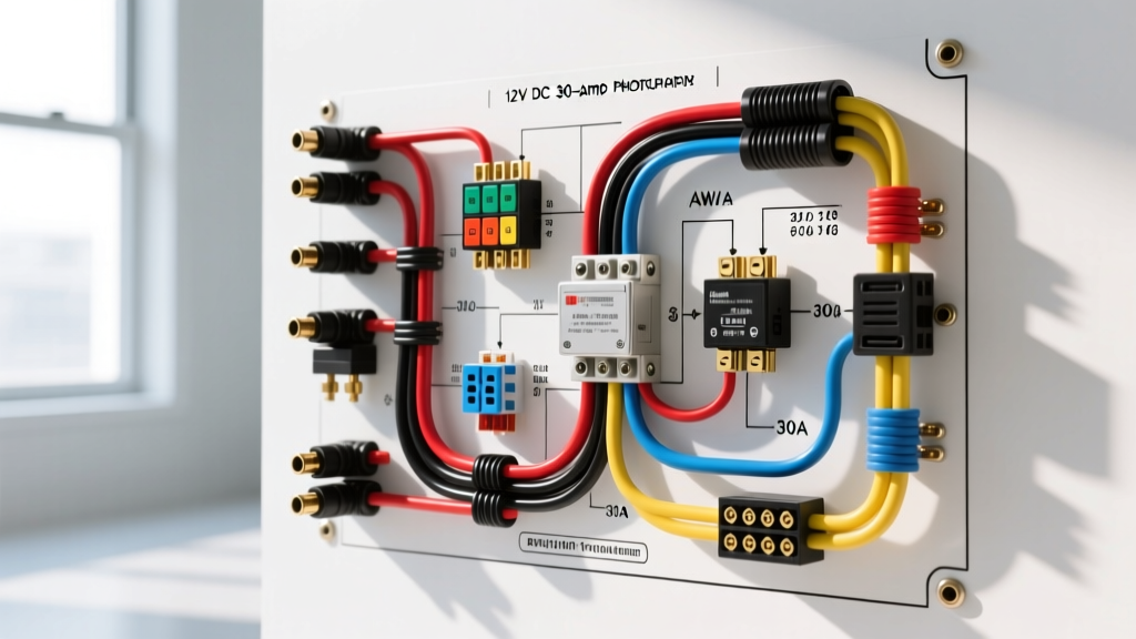
Introduction to RV 12V DC 30-Amp Audio Circuits
When mobile audio enthusiasts search for an RV 30 amp wiring diagram, they are typically met with schematics for 120V AC shore power (NEMA TT-30P). However, in the context of high-output car audio and stereo integration within a recreational vehicle, a "30-amp wiring diagram" refers to the critical 12V DC circuit required to power a mid-tier to high-tier audio amplifier. Whether you are installing a 500W RMS Class-D monoblock subwoofer amplifier or a multi-channel Class-AB amp for an RV living area, designing a dedicated 30-amp DC circuit requires strict adherence to mobile electrical standards.
Recreational vehicles present unique electrical challenges compared to standard passenger cars. The extreme distances between the engine bay alternator, the house battery bank, and the rear living quarters introduce severe voltage drop. Furthermore, RV chassis construction—often utilizing a mix of steel I-beams, aluminum framing, and fiberglass tubs—makes traditional chassis grounding highly unreliable. This technical specification reference outlines the exact topology, wire gauges, overcurrent protection, and termination standards required to safely deploy a 30-amp 12V DC audio circuit in an RV environment.
Core RV 30 Amp Wiring Diagram: Component Topology
A safe and efficient 12V DC audio circuit must follow a strict point-to-point topology. Never tap into the RV's existing 12V lighting or accessory circuits, as these are typically limited to 15A or 20A and utilize undersized 14 AWG or 12 AWG wiring that will melt under the sustained load of an audio amplifier.
- Power Source: Direct connection to the RV's primary house battery bank or a dedicated auxiliary AGM/LiFePO4 audio battery.
- Main Overcurrent Protection: A 35A or 40A time-delay ANL fuse mounted within 18 inches of the positive battery terminal.
- Primary Power Wire: Marine-grade, tinned copper wire routed through the chassis I-beam using split-loom tubing and EPDM rubber grommets.
- Firewall/Chassis Penetration: Sealed with a marine-grade deck gland or rubber grommet to prevent moisture ingress and wire chafing.
- Amplifier Integration: Direct termination into the amplifier's positive power set-screw, utilizing a tinned copper ring terminal.
Wire Gauge and Voltage Drop Calculations
According to SAE J1128 standards for low-tension primary cable, wire gauge selection must account for the total round-trip distance (positive + negative) of the circuit. In an RV, an amplifier mounted in the rear bedroom may be 25 feet away from the front engine battery, resulting in a 50-foot total circuit length. To maintain a voltage drop below 3% (0.36V on a 12V system) at a continuous 30-amp draw, you must oversize the wire.
| AWG Size | Wire Type | Max Run (12V @ 30A) | Voltage Drop @ 20ft | Application |
|---|---|---|---|---|
| 8 AWG | OFC (Oxygen-Free Copper) | 12 feet | 0.60V (5.0%) | Short runs, cabin dash setups |
| 6 AWG | OFC / Tinned Marine | 20 feet | 0.40V (3.3%) | Standard RV mid-cabin audio |
| 4 AWG | OFC / Tinned Marine | 35 feet | 0.24V (2.0%) | Long RV runs (Engine to Rear) |
| 2 AWG | Tinned Marine (UL 1426) | 50+ feet | 0.15V (1.25%) | Class-AB amps, high-transient setups |
Note: Never use CCA (Copper-Clad Aluminum) wire in an RV. The high vibration and thermal cycling of an RV chassis will cause CCA wire to work-harden, snap, and create high-resistance points that lead to fires.
DC Distribution and Overcurrent Protection
While the continuous draw of your audio system may be calculated at 30 amps, musical transients (heavy bass notes) can cause instantaneous current spikes exceeding 45 amps for milliseconds. Therefore, the ABYC E-11 standard for DC electrical systems in mobile environments recommends utilizing time-delay fuses for inductive and capacitive loads like audio amplifiers.
Fuse Selection Matrix
- 35A ANL Fuse: Ideal for Class-D amplifiers with high-efficiency switching power supplies. The ceramic body and bolt-down design withstand RV chassis vibrations better than glass AGU fuses.
- 40A Circuit Breaker (Marine Rated): Acceptable for easy reset capabilities, but must be mounted in a dry, enclosed compartment. Standard automotive breakers will corrode internally in humid RV environments.
- Secondary Fusing: If utilizing a distribution block to feed multiple amplifiers, each branch circuit must have its own inline fuse rated for the specific AWG of the branch wire (e.g., a 20A ATC fuse for a 12 AWG branch wire).
Chassis Grounding vs. Direct Battery Return
The most common failure point in RV audio installations is the ground connection. In a standard unibody car, the steel chassis provides a massive, low-resistance return path to the battery. In an RV, this is rarely the case. Many motorhomes and travel trailers utilize aluminum cage construction, powder-coated steel frames, or fiberglass floors. Furthermore, the connection between the house battery negative and the chassis is often undersized or corroded.
The RV Audio Grounding Rule: Always run a dedicated negative return wire directly from the amplifier's ground terminal to the nearest verified chassis ground point, and ensure that the chassis is bonded to the battery negative with at least 2 AWG wire. If the RV features a fiberglass or composite floor, you must run a dedicated 4 AWG ground wire the entire distance back to the house battery bank's negative busbar. Paint, rust, and anodized aluminum are electrical insulators; any chassis ground point must be sanded down to bare, shiny metal and coated with dielectric grease after torquing the terminal to 8-10 Nm.
Termination Standards and Corrosion Prevention
RVs are subjected to extreme environmental conditions, including high humidity, road salt, and severe vibration. According to NFPA 70 (NEC) Article 551 regarding recreational vehicles, all mobile wiring must be protected against physical damage and corrosion. For audio wiring, this mandates the following termination protocol:
- Wire Stripping: Use a precision wire stripper that does not nick the copper strands. Nicked strands reduce the cross-sectional area and create localized heat points.
- Terminal Selection: Use only heavy-wall, adhesive-lined, tinned copper ring terminals. The tin plating prevents galvanic corrosion when mating with nickel-plated amplifier set-screws.
- Crimping: Use a dedicated hex-crimp tool. Never solder crimp terminals in high-vibration environments; solder wicks into the wire strands, creating a rigid point that will eventually snap under chassis flex.
- Heat Shrinking: Apply 3:1 ratio dual-wall adhesive heat shrink over the crimp barrel. The inner meltable adhesive creates a waterproof seal, preventing capillary action from drawing moisture into the wire jacket.
Troubleshooting Voltage Drop in RV Audio Setups
When an RV audio system exhibits clipping, thermal shutdown, or dimming lights, use this diagnostic matrix to isolate the fault.
| Symptom | Root Cause | Diagnostic Step | Resolution |
|---|---|---|---|
| Amplifier Protect Mode on heavy bass | Voltage drop below 10.5V at amp terminals | Measure DC voltage at amp posts with DMM during bass transient | Upgrade to 4 AWG OFC wire; add auxiliary capacitor or LiFePO4 battery |
| Alternator whine in audio signal | Ground loop via RV chassis or poor RCA shielding | Check resistance between amp ground and battery negative (should be <0.1 ohms) | Clean chassis ground; run dedicated ground wire; check RCA routing away from 120V AC lines |
| Wire jacket melting or warm to touch | Undersized wire or loose termination causing high resistance | Inspect crimps for oxidation; measure voltage drop across fuse and terminals | Re-terminate with hex-crimp tool; upgrade wire gauge; apply dielectric grease |
| ANL Fuse blowing randomly | Use of fast-acting fuse on capacitive load | Verify fuse type and amplifier RMS current draw | Replace with time-delay ANL fuse; verify no short in power wire grommets |
Summary of Best Practices
Executing a proper RV 30 amp wiring diagram for a 12V audio system requires abandoning standard automotive shortcuts in favor of marine-grade methodologies. By utilizing tinned OFC wire, adhesive-lined terminations, time-delay ANL fusing, and dedicated battery return paths, you ensure that your RV's audio system delivers pristine, uninterrupted power regardless of the terrain or environmental conditions. Always verify your specific RV's chassis bonding and house battery capacity before finalizing your amplifier's power delivery network.