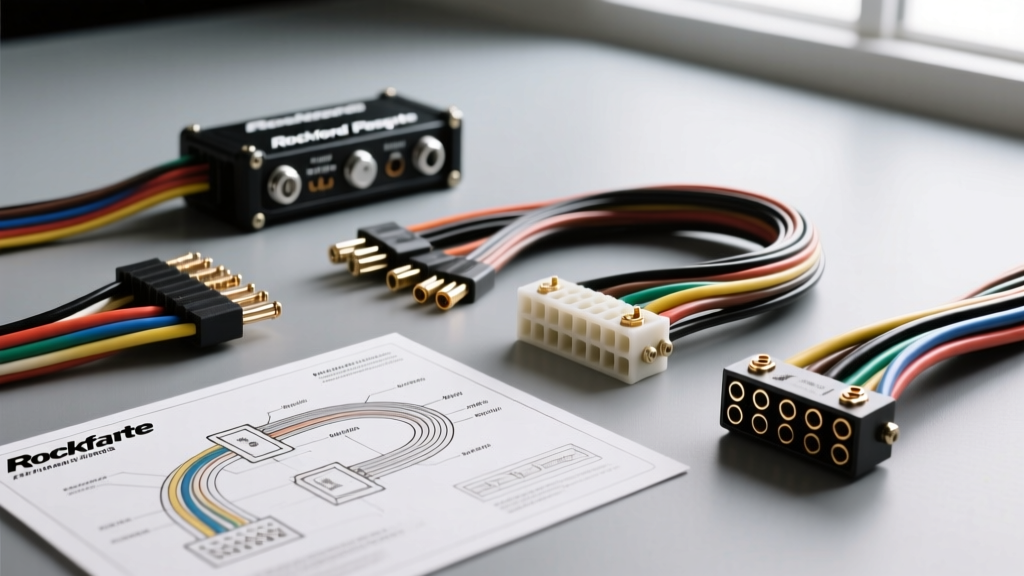
Decoding the Rockford Fosgate Amp Wiring Diagram Ecosystem
When planning a high-fidelity mobile audio build, interpreting a rockford fosgate amp wiring diagram correctly is just the first step. Rockford Fosgate segments its amplifier lineup into three distinct tiers: Prime, Punch, and Power. Each series features unique terminal architectures, thermal management systems, and input topologies. Selecting the right amplifier requires matching your vehicle's electrical capabilities and acoustic goals with the specific wiring requirements of each series. This guide breaks down the physical and electrical differences between these lines, providing actionable wiring specifications, torque values, and integration strategies for professional-grade installations.
Series Comparison: Prime vs. Punch vs. Power
Before running power wire through your vehicle's firewall, you must understand how the internal topology and terminal blocks differ across the Rockford Fosgate lineup. The wiring diagram for a Prime R-Series amplifier will look vastly different from a Power T-Series monoblock, particularly regarding gauge limits and input pinouts.
Rockford Fosgate Prime Series (R-Series)
The Prime series is engineered for OEM integration and budget-conscious builds. These amplifiers utilize compact Class-D topology and feature smaller set-screw terminals.
- Terminal Capacity: Accepts up to 8 AWG power and ground wire.
- Input Harness: Features a proprietary Molex-style connector for speaker-level inputs. Pinout: Pin 1 (Left +), Pin 2 (Left -), Pin 3 (Right +), Pin 4 (Right -). This harness includes an auto-turn-on circuit that detects DC offset or audio signal from the factory head unit.
- Best Application: Upgrading factory 4-channel door speakers or adding a modest 300W enclosed subwoofer without upgrading the vehicle's alternator.
Rockford Fosgate Punch Series (P-Series)
The Punch series represents the core of Rockford Fosgate's lineup, featuring C.L.E.A.N. (Calibrated Level Eliminates Audible Noise) technology and dual-fan forced-air cooling. The wiring diagrams for Punch amps emphasize signal integrity and high-current delivery.
- Terminal Capacity: Accepts up to 4 AWG power and ground wire, utilizing large brass set-screws.
- C.L.E.A.N. Input Pinout: The Punch series uses a standard RCA input alongside a speaker-level input harness. When using the C.L.E.A.N. setup, the amplifier generates internal test tones. The input gain must be adjusted until the C.L.E.A.N. LED indicator shifts from red (clipping) to green (optimized voltage).
- Best Application: High-output daily drivers requiring 600W to 1200W RMS, where alternator output is between 130A and 160A.
Rockford Fosgate Power Series (T-Series)
The Power series is built for SPL (Sound Pressure Level) competitions and extreme audiophile builds. The wiring diagrams for T-Series amps often feature dual power inputs, differential RCA architectures, and massive MEHSA (Maximum Efficiency Heat Sink Architecture) extrusions.
- Terminal Capacity: Accepts 1/0 AWG or dual 4 AWG power and ground wires. The set-screws are hex-drive and require precise torque to prevent wire strand shearing.
- Differential Inputs: Power series amps utilize differential RCA inputs. Unlike standard single-ended RCAs, differential inputs measure the voltage difference between the signal and the ground shield, providing a high Common Mode Rejection Ratio (CMRR) that eliminates alternator whine without needing ground loop isolators.
- Best Application: Multi-kilowatt subwoofer arrays requiring dedicated high-output alternators and 0-gauge OFC distribution blocks.
Terminal & Wire Gauge Specifications Chart
Adhering to the correct wire gauge and torque specifications is critical. Under-torquing set-screws leads to high-resistance connections, voltage drops, and melted terminal blocks. The following chart outlines the mechanical and electrical limits based on SAE J1128 Battery Cable Standards and Rockford Fosgate engineering specifications.
| Amplifier Series | Max Power/Ground AWG | Set-Screw Torque Spec | Recommended Main Fuse | Input Architecture |
|---|---|---|---|---|
| Prime (R-Series) | 8 AWG | 12-15 in-lbs | 40A - 60A (Mini-ANL) | Speaker-Level (Auto-Sense) |
| Punch (P-Series) | 4 AWG | 20-25 in-lbs | 80A - 150A (ANL) | RCA + C.L.E.A.N. Speaker-Level |
| Power (T-Series) | 1/0 AWG (or Dual 4 AWG) | 35-45 in-lbs | 200A - 300A (Class-T / ANL) | Differential RCA / Balanced |
Step-by-Step Wiring Selection for Your Build
Once you have selected your amplifier series, the physical routing and material selection of your wiring must align with the amp's current draw. According to Rockford Fosgate official installation manuals, the following practices ensure optimal current delivery and signal fidelity.
Power and Ground Routing (OFC vs. CCA)
Always use Oxygen-Free Copper (OFC) wire for mobile audio installations. Copper-Clad Aluminum (CCA) wire has a higher electrical resistance, which causes severe voltage drop over long runs. For a Punch P1000x1 monoblock drawing roughly 120 amps at 14.4V, a 4 AWG OFC wire run of 15 feet will experience a voltage drop of less than 0.2V. The same run using CCA wire will drop nearly 0.4V, triggering the amplifier's under-voltage protection circuit during heavy bass transients. Route the main power wire through the firewall using a rubber grommet, and secure it every 12 inches with zip ties to prevent chassis chafing.
Remote Turn-On & Signal Inputs
The remote turn-on wire (typically 18 AWG, blue with a white stripe) signals the amplifier to power up. If your head unit lacks a dedicated remote output, you can tap into the vehicle's ignition-switched fuse box using an add-a-fuse adapter. Never connect the remote wire to a constant 12V source, as this will drain the vehicle's battery. For signal inputs, keep RCA cables on the opposite side of the vehicle from the power wire to prevent electromagnetic interference (EMI). If crossing the power wire is unavoidable, do so at a strict 90-degree angle.
Common Wiring Mistakes & Troubleshooting
Even with a perfect rockford fosgate amp wiring diagram in hand, installation errors can lead to protection mode activation. Use the amplifier's built-in LED diagnostic indicators to troubleshoot real-world failure modes:
- Solid Red LED (Thermal Protection): The amplifier has exceeded its safe operating temperature (typically 140°F / 60°C). Fix: Check for inadequate airflow, impedance mismatch (e.g., wiring a 1-ohm load to a 2-ohm stable Punch amp), or a clipped signal causing excessive voice coil heat.
- Flashing Red LED (Short Circuit Protection): The output stage has detected a dead short. Fix: Disconnect all speaker wires at the amplifier. If the LED remains flashing, the internal MOSFETs are blown. If the LED turns green, the short is in the speaker wire routing. Check for pinched wires under rear seat brackets or in the trunk hinge.
- No LED / No Power: Fix: Use a digital multimeter to measure voltage directly at the amplifier's B+ and GND terminals while the system is attempting to turn on. If voltage is below 10.5V, inspect the main fuse, the distribution block connections, and the chassis ground point. Ensure the chassis ground is sanded down to bare metal and secured with a star washer to bite through the factory paint and primer.
Final Integration Notes
Mastering your installation requires respecting the engineering limits defined in the amplifier's schematic. Whether you are utilizing the auto-sense speaker-level inputs on a Prime R2-500x4 or configuring the differential RCAs on a Power T1500-1bdCP, proper wire gauge selection, precise terminal torque, and clean signal routing are non-negotiable. For further technical validation on mobile amplifier power ratings, refer to the Consumer Technology Association's CEA-2006 standards, which dictate how manufacturers like Rockford Fosgate measure and certify RMS power output across varying impedance loads.