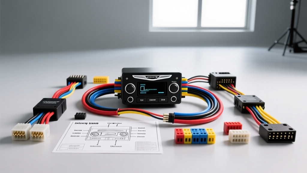
Advanced Architecture: The 2013 Chrysler 200 Audio Network
Integrating an aftermarket head unit into a 2013 Chrysler 200 requires far more than matching speaker wire colors. The JS-platform Chrysler 200 relies heavily on the CAN IHS (Interior High Speed) data bus to manage not only steering wheel controls and EVIC (Electronic Vehicle Information Center) displays but also critical vehicle chimes and anti-theft immobilizer handshakes. Whether you are working with the base 4-speaker system, the Uconnect 430/730N multimedia hub, or the premium Infinity audio package, understanding the 2013 Chrysler 200 radio wiring diagram at a circuit level is mandatory to avoid triggering U0184 (Lost Communication With Radio) diagnostic trouble codes.
This technical deep dive bypasses generic installation advice, providing exact C2 connector pinouts, Infinity amplifier bypass protocols, and CAN bus interface requirements sourced from Mopar Connection Repair Kits and OEM service documentation.
Primary Radio Harness Pinout (Connector C2 - 22 Pin)
The main interface between the Uconnect radio and the vehicle's body control module (BCM) and power distribution center is the 22-pin C2 connector. Below is the definitive pinout for the 2013 model year. Note that Chrysler utilizes specific twisted-pair shielding for the CAN IHS network to prevent electromagnetic interference (EMI) from the ignition system.
| Pin | Wire Color | Circuit Function | AWG / Notes |
|---|---|---|---|
| 1 | White/Red | CAN IHS (+) | 20 AWG (Twisted Pair) |
| 2 | White/Black | CAN IHS (-) | 20 AWG (Twisted Pair) |
| 3 | Dark Green/Red | Left Front Speaker (+) | 18 AWG |
| 4 | Dark Green/Black | Left Front Speaker (-) | 18 AWG |
| 5 | Dark Green/Orange | Left Rear Speaker (+) | 18 AWG |
| 6 | Dark Green/Brown | Left Rear Speaker (-) | 18 AWG |
| 11 | Pink/White | Fused B(+) (Constant 12V) | 18 AWG (Upgrade to 12 AWG) |
| 12 | Black/Light Green | Ground (G201) | 18 AWG (Upgrade to 12 AWG) |
| 13 | Purple/White | Right Front Speaker (+) | 18 AWG |
| 14 | Purple/Black | Right Front Speaker (-) | 18 AWG |
| 15 | Purple/Orange | Right Rear Speaker (+) | 18 AWG |
| 16 | Purple/Brown | Right Rear Speaker (-) | 18 AWG |
| 22 | Dark Blue/Pink | Fused Ignition Run/Start | 18 AWG (Switched 12V) |
Note: Pins 7-10 and 17-21 are typically reserved for satellite radio (UConnect 730N), rear-seat entertainment, or auxiliary audio inputs and may be unpopulated on base models.
The Infinity Amplifier Bypass Protocol
The most frequent point of failure in Chrysler 200 audio upgrades occurs when installers fail to identify the factory Infinity premium audio system. The Infinity system utilizes a remote Class-D amplifier located in the trunk (driver-side rear quarter panel). The head unit outputs low-level (line-level) audio signals via a separate harness, which the amplifier processes and drives the speakers.
If you connect standard high-level aftermarket speaker wires to the C2 connector on an Infinity-equipped vehicle, you will have no audio output. You have two technical solutions:
Solution A: Active Line Output Conversion (Recommended)
Use an active data-bus interface like the PAC Audio RP4-CR11 or Axxess AX-ABFD1. These modules intercept the digital audio data on the CAN bus and the analog low-level signals, converting them to standard RCA pre-outs while retaining the factory chime and steering wheel control (SWC) data. This preserves the signal-to-noise ratio (SNR) and prevents alternator whine.
Solution B: Hardwire Bypass (High Labor)
If bypassing the amplifier manually, you must pull the rear seat cushion and trunk trim to access the Infinity amp. Disconnect the 14-pin output connector at the amp and run new 16 AWG OFC (Oxygen-Free Copper) speaker wires from the dash C2 connector, through the vehicle's left-side sill plate conduit, directly to the trunk. You must also splice the remote turn-on lead (Pin 22 switched 12V) to trigger your new aftermarket amplifier. Warning: Bypassing the Infinity amp without a chime-retention module will result in the loss of door-ajar chimes and turn signal clicks, as these are generated by the radio/amp network.
CAN IHS Data Bus and Steering Wheel Controls
The 2013 Chrysler 200 does not use a dedicated analog resistance-ladder wire for steering wheel controls. Instead, the steering wheel clock spring communicates via LIN (Local Interconnect Network) to the steering column control module (SCCM), which then broadcasts the SWC commands onto the CAN IHS bus (Pins 1 and 2 on the C2 connector).
To retain SWC functionality with an aftermarket Pioneer, Kenwood, or Alpine head unit, a digital translation module is required. The module must be wired in parallel to the CAN IHS twisted pair. Do not cut the factory CAN wires. Use T-taps or carefully strip the insulation and solder the interface module's CAN wires, ensuring the twist rate of the factory wiring is maintained to prevent bus termination errors. For deeper fitment and interface compatibility data, the Crutchfield Vehicle Fit Database remains an excellent cross-reference for module selection.
Power and Ground AWG Upgrades
The factory Uconnect radio draws minimal current, which is why Chrysler utilizes 18 AWG wiring for the constant B(+) (Pin 11) and Ground (Pin 12). However, modern aftermarket double-DIN multimedia receivers with 7-to-10-inch capacitive touchscreens, internal 4x50W MOSFET amplifiers, and Wi-Fi modules can draw upwards of 15-18 amps under peak load.
- Power Upgrade: Run a dedicated 12 AWG primary wire from the interior fuse panel (using an Add-A-Circuit on a 20A constant fuse slot) to the radio cavity. Splice this into the Pink/White wire within 6 inches of the head unit harness.
- Ground Upgrade: The factory ground terminates at G201 behind the driver's side kick panel. Over time, galvanic corrosion increases resistance at this node. Run a dedicated 12 AWG ground wire from the radio harness to a clean, bare-metal chassis point behind the dash, securing it with a zinc-plated ring terminal and an M6 flange bolt torqued to 7-9 Nm.
Diagnostic Troubleshooting Decision Tree
When post-installation anomalies occur, use this structured diagnostic approach before pulling the dash trim again.
| Symptom | Probable Cause | Technical Fix / Verification |
|---|---|---|
| Radio turns on, but no audio from any speaker. | Infinity Amp not triggered, or low-level signal mismatch. | Verify remote turn-on wire (Blue/White) is receiving +12V during RUN. Check if factory amp bypass harness is fully seated in the trunk. |
| U0184 DTC stored in BCM; EVIC displays 'Service Radio'. | CAN IHS bus termination failure or short. | Measure resistance between Pin 1 and Pin 2 at the C2 connector (ignition OFF). Should read ~60 ohms. If 120 ohms, a bus module is disconnected. If 0 ohms, CAN wires are shorted. |
| Parasitic battery draw (Radio stays on after vehicle sleep). | Aftermarket radio failing to detect CAN bus 'Sleep' command. | Ensure the aftermarket radio's 'CAN Bus' setting in the hidden OEM menu is enabled, or verify the interface module is correctly passing the IGN OFF data packet. |
| Alternator whine in audio signal that pitches with RPM. | Ground loop via factory Infinity amp ground. | Isolate the RCA grounds. Ensure aftermarket amp ground and head unit ground share the same chassis potential. Do not ground to painted seatbelt bolts. |
Final Installation Verification
Before reassembling the center console and HVAC trim bezels, perform a full network scan using an OBD-II scanner capable of reading Chrysler-specific CAN modules. Clear any historical U-codes generated during the battery disconnect phase. Verify that the TPMS (Tire Pressure Monitoring System) EVIC display populates correctly on the new head unit screen, as this data is routed through the same CAN IHS gateway as the audio telemetry. Proper execution of this 2013 Chrysler 200 radio wiring diagram ensures a factory-grade integration with superior aftermarket acoustic performance.