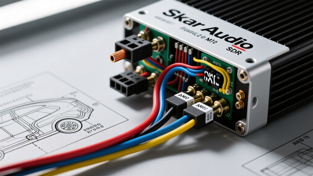
Choosing the Right Skar Audio Amplifier Topology
When integrating high-output aftermarket bass into a vehicle's electrical architecture, interpreting a Skar amp wiring diagram is only half the battle. The foundation of a reliable mobile audio system lies in matching the amplifier's topology and efficiency class to your vehicle's charging system and acoustic goals. Skar Audio offers several distinct amplifier series, each with unique power draw characteristics, terminal layouts, and thermal management profiles. Selecting the wrong series for your electrical setup can result in severe voltage sag, thermal shutdown, or alternator failure.
This guide compares the flagship Skar Audio series and provides an exhaustive breakdown of their wiring diagrams, terminal specifications, and integration requirements for modern vehicle platforms.
Skar Audio Series Comparison: RP vs. SDR vs. IX
Before cutting into your vehicle's harness or routing power wire through the firewall, you must understand the electrical demands of your chosen amplifier. The table below contrasts the three primary Skar Audio monoblock lines based on a 1500-watt RMS benchmark.
| Specification | RP-1500.1D (Reference) | SDR-1500.1D (Budget) | IX-1500.1D (Micro) |
|---|---|---|---|
| Class Topology | Class D (High Efficiency) | Class D (Standard) | Class D (Micro-Drive) |
| Peak Efficiency | > 90% | ~ 80% | ~ 85% |
| Max Current Draw (13.8V) | ~ 130 Amps | ~ 145 Amps | ~ 140 Amps |
| Recommended Power Wire | 1/0 AWG OFC | 4 AWG (Short) / 1/0 AWG (Long) | 4 AWG OFC |
| Terminal Type | Set-Screw (Brass) | Set-Screw (Brass) | Set-Screw (Brass) |
| Best Application | Competition SPL / Daily High-Output | Budget Daily Drivers | Stealth / Under-Seat Installations |
According to the CTA-2006-C Mobile Audio Power Standard, amplifier ratings must be measured at 14.4V with a maximum 1% THD+N. However, real-world vehicle resting voltage is often 12.6V, and under heavy bass transients, it can drop below 11.5V. The RP series' superior efficiency means it generates less waste heat and draws less amperage from the alternator, making it the superior choice for vehicles with stock 110A-130A alternators.
Decoding the Standard Skar Amp Wiring Diagram
While specific pinouts vary slightly between the RP, SDR, and IX lines, the fundamental Skar amp wiring diagram relies on a standardized terminal block layout. Understanding the exact function and preparation method for each terminal is critical to preventing arcing, voltage drop, and thermal runaway.
Power (BATT) and Ground (GND) Terminals
The primary power and ground terminals on Skar amplifiers are designed to accept up to 1/0 AWG stranded copper wire. These are set-screw terminals, not compression clamps.
- Terminal Preparation: Never 'tin' the ends of your stranded power wire with solder. Solder is a soft metal that deforms under the pressure of a set screw, leading to a loose connection over time due to thermal cycling and vehicle vibration. Instead, use closed-end copper ferrules crimped with a hex-crimper.
- Torque Specification: The brass set screws require approximately 3.5 to 4.5 Nm (30-40 in-lbs) of torque. Over-tightening will strip the brass threads; under-tightening will cause high resistance, leading to localized melting of the acrylic terminal block.
- Grounding Protocol: The GND wire must be terminated with a 5/16-inch copper ring terminal, bolted directly to bare, unpainted chassis metal or a dedicated seat-belt anchor bolt. Use a star washer to bite through any residual zinc coating or e-coat. The ground wire length should never exceed 3 feet to minimize ground loop potential.
Remote Turn-On (REM) and RCA Inputs
The REM terminal accepts 18 to 12 AWG wire. This circuit triggers the amplifier's internal power supply. It draws less than 50mA, so heavy-gauge wire is unnecessary. Standard CEA mobile electronics color coding dictates using Blue with a White Stripe for the remote turn-on lead from the aftermarket head unit. If integrating with a factory OEM radio (e.g., Ford Sync 3 or GM Bose), you must tap into a switched 12V+ fuse (like the windshield wiper or accessory outlet) using an add-a-fuse, or use a DC signal-sensing remote turn-on module.
Wire Gauge (AWG) Selection Chart for Skar Amplifiers
Voltage drop is the enemy of Class D amplifiers. When voltage drops below 11.0V, the Skar amplifier's internal protection circuit will engage, flashing the LED indicator red and shutting down the audio output. The following chart dictates the minimum SAE J1128 compliant Oxygen-Free Copper (OFC) wire gauge required based on the amplifier's total RMS wattage and the total length of the power wire run (from battery to amp).
| Total System RMS Wattage | 0 - 10 Feet | 10 - 16 Feet | 16 - 22 Feet | 22+ Feet |
|---|---|---|---|---|
| Up to 600W (e.g., SDR-600.1D) | 8 AWG | 8 AWG | 4 AWG | 4 AWG |
| 600W - 1200W (e.g., RP-1200.1D) | 4 AWG | 4 AWG | 2 AWG | 1/0 AWG |
| 1200W - 2000W (e.g., RP-1500.1D) | 2 AWG | 1/0 AWG | 1/0 AWG | 2/0 AWG |
| 2000W - 3500W (e.g., RP-3500.1D) | 1/0 AWG | 1/0 AWG | 2/0 AWG | 2/0 AWG (Dual Run) |
Note: Copper-Clad Aluminum (CCA) wire has roughly 30% higher electrical resistance than OFC. If you must use CCA wire, you must step up one full AWG size across all measurements to compensate for the voltage drop.
OEM Head Unit Integration & Signal Summing
Modern vehicles rarely offer clean, unamplified pre-out signals. If you are wiring a Skar amplifier into a factory amplified system (such as a Ram Alpine or Chevy Bose), the factory subwoofer output is often crossed over, equalized, and phase-shifted. Feeding this directly into the RCA inputs of your Skar amp will result in muddy, inaccurate bass.
To correct this, your wiring diagram must include a Digital Signal Processor (DSP) or a high-quality Line Output Converter (LOC) with signal summing capabilities.
- Signal Extraction: Tap the factory subwoofer positive and negative wires (typically Purple/Green and Purple/Brown on GM platforms) using T-taps or solder-and-shrink tubing.
- Summing: Route these into the LOC/DSP. The device will sum the left and right channels and flatten the factory EQ curve.
- RCA Routing: Run shielded, twisted-pair RCA cables from the DSP to the Skar amp's L and R RCA inputs. Crucial: Route RCA cables down the opposite side of the vehicle's interior from the main power wire to prevent electromagnetic interference (EMI) and alternator whine.
Electrical System Upgrades: The 'Big 3' Wiring
If your Skar amp wiring diagram includes an RP-2000.1D or larger, your vehicle's stock electrical system will likely fail to keep up with transient bass hits. Before upgrading the alternator, you must perform the 'Big 3' Wiring Upgrade to eliminate factory bottlenecks.
- Alternator POS to Battery POS: Replace or supplement the factory wire with 1/0 AWG OFC. This allows the alternator to deliver maximum current directly to the battery bank.
- Engine Block to Chassis: The engine block grounds the alternator casing. Add a 1/0 AWG ground strap from the alternator casing or engine block to the bare chassis.
- Battery NEG to Chassis: Add a 1/0 AWG ground wire from the battery negative terminal to a clean, bare metal point on the chassis near the battery.
Diagnostic Troubleshooting: LED Status Codes
When the installation is complete, turn on the head unit. The LED on the side of the Skar amplifier will indicate the status of the internal circuits:
- Solid Blue: Normal operation. Power, ground, and remote signals are within acceptable parameters (11.5V - 15.5V).
- Flashing Red: Protection mode engaged. This indicates either a short circuit in the speaker wire (check for stray strands touching the chassis), an impedance load below the amp's stable limit (e.g., wiring dual 2-ohm subs in parallel for a 1-ohm load on an amp only stable to 2-ohms), or severe thermal overload.
- Off (No Light): No power reaching the board. Use a digital multimeter to check voltage between the BATT and GND terminals on the amp itself. If you read 0V, check the main ANL fuse near the battery. If you read 12V but the amp is off, check the REM terminal for switched 12V.
By meticulously following these wiring protocols, respecting AWG distance charts, and utilizing proper terminal preparation techniques, your Skar Audio amplifier will deliver reliable, distortion-free power for the lifespan of the vehicle.