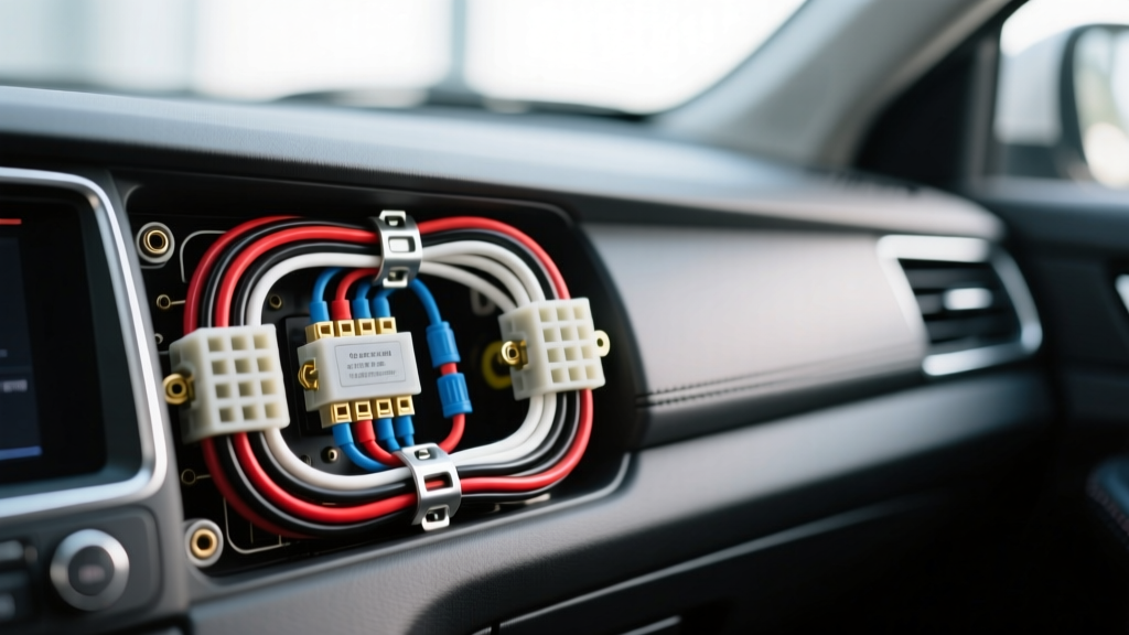
The Systematic Approach to Car Speaker Wiring Diagnostics
When an aftermarket head unit or external amplifier fails to produce sound, or when the audio output is plagued by distortion and weak bass, the root cause is frequently traced back to the vehicle's speaker harness. Diagnosing car speaker wiring requires a methodical, step-by-step troubleshooting flow rather than random guesswork. Modern vehicles utilize complex multiplexed networks, active crossovers, and fragile low-tension primary cables that can easily fail due to environmental stress or improper aftermarket integration. This guide provides an automotive electrical expert's decision tree for isolating open circuits, short-to-ground faults, and phase cancellations in 16 AWG to 18 AWG mobile audio circuits.
Phase 1: Pre-Test Visual and Physical Inspection
Before introducing a multimeter into the circuit, you must eliminate physical failure points. The most common point of failure in OEM car speaker wiring is the door jamb harness boot. Every time the vehicle door is opened and closed, the wiring bundle flexes. Over time, the copper strands inside 18 AWG factory wire can fatigue and snap, creating an intermittent open circuit.
- Connector Pin Inspection: Disconnect the main harness at the head unit or amplifier. Inspect the Molex MX150 or Delphi Packard terminals for green copper oxide (corrosion) or backed-out pins. A backed-out pin will not make contact with the male blade, resulting in a dead channel.
- Crimp vs. Solder Joints: If troubleshooting an aftermarket installation, inspect all butt connectors and crimp caps. Tug gently on the wire; a proper crimp should withstand 15-20 lbs of pull force. If the wire slides out, the connection has high resistance and will cause thermal voltage drop and audio clipping.
- Chafing and Ground Shorts: Trace the speaker wire routing near the kick panels and seat rails. Sharp metal edges can easily slice through thin PVC wire insulation, causing the negative speaker terminal to short directly to the vehicle's steel chassis.
Phase 2: Multimeter Troubleshooting Decision Tree
Set your digital multimeter (DMM) to the appropriate testing mode based on the specific audio symptom you are experiencing. Never test speaker wiring with the amplifier powered on and connected to the speakers, as the AC audio signal can damage the DMM's internal fuse or skew continuity readings.
Symptom A: Complete Silence (Open Circuit)
- Step 1 (Source Verification): Disconnect the speaker wire from the amplifier terminal. Set the DMM to AC Voltage (20V scale). Play a 60Hz or 1kHz test tone at 50% volume. Probe the amplifier's speaker terminals. For a 50W RMS amplifier driving a 4-ohm load, you should read approximately 14.14V AC (calculated via V = √(P × R)). If you read 0V, the fault is internal to the amplifier or head unit, not the wiring.
- Step 2 (Continuity Check): If the amp outputs voltage, reconnect the wire to the amp. Go to the speaker location and disconnect the speaker. Set the DMM to Continuity/Ohms. Probe the positive and negative wires. You should read an open loop (OL). If you read near 0 ohms, the wires are shorted together somewhere in the harness.
- Step 3 (Wire Integrity): To test for a broken wire, use a long jumper wire to bridge the positive and negative terminals at the speaker end. Return to the amplifier end and test for continuity. If the meter reads OL, you have a severed wire, likely in the door jamb boot.
Symptom B: Distorted or Intermittent Audio (Short to Ground)
Many modern Class-D amplifiers and OEM head units feature short-circuit protection that will mute a channel if the negative speaker wire touches the chassis ground.
- Disconnect both ends of the suspect speaker wire (at the amp and at the speaker).
- Set the DMM to Continuity.
- Place the black probe on a known good chassis ground (bare, unpainted metal).
- Probe the positive and negative speaker wires individually with the red probe.
- Result: The meter should read OL. If it beeps or shows low resistance, the wire's insulation has been compromised and is shorting to the vehicle body. You must re-route the wire or replace the harness.
Symptom C: Weak Bass and Hollow Soundstage (Out of Phase)
If the car speaker wiring is reversed (positive connected to negative), the speakers will be 180 degrees out of phase. This causes acoustic cancellation, severely reducing bass response.
- The 9V Battery Test: Disconnect the speaker wires from the amplifier. Momentarily tap a standard 9V battery across the positive and negative wires at the amplifier end. Have an assistant watch the speaker cone. If the cone pushes outward, the battery's positive terminal matches the wire's positive polarity. If the cone pulls inward, the polarity is reversed.
OEM vs. Aftermarket Car Speaker Wiring Reference Chart
Understanding wire gauge specifications and standard OEM color codes is critical for efficient troubleshooting. The following table outlines the electrical characteristics of common automotive speaker wire gauges, referencing the SAE J1128 standard for Low Tension Primary Cable.
| Wire Gauge (AWG) | Cross-Section (mm²) | Resistance (Ohms/1000ft) | Max Power (4-Ohm Load) | Typical Application |
|---|---|---|---|---|
| 18 AWG | 0.82 mm² | 6.38 Ω | 25W RMS | OEM Low-Power Head Units |
| 16 AWG | 1.31 mm² | 4.01 Ω | 75W RMS | Standard Aftermarket / Premium OEM |
| 14 AWG | 2.08 mm² | 2.52 Ω | 150W RMS | High-Power Component Systems |
Standard General Motors (GM) Non-Amplified Wire Colors
When diagnosing GM vehicles (Silverado, Tahoe, Malibu) without factory amplifiers, utilize this standard color code to verify correct pinout at the Metra 70-1858 harness adapter:
- Left Front: Tan (+) / Gray (-)
- Right Front: Light Green (+) / Dark Green (-)
- Left Rear: Brown (+) / Yellow (-)
- Right Rear: Dark Blue (+) / Light Blue (-)
Phase 3: Advanced Failure Modes in Factory Amplified Systems
Troubleshooting car speaker wiring becomes significantly more complex when dealing with factory-amplified systems (e.g., Bose, Infinity, Harman Kardon). These systems often utilize 2-ohm or even 1-ohm voice coils and active, low-voltage crossovers built into the factory amplifier.
If you are extracting a high-level signal from a factory amplified system to feed an aftermarket DSP or line output converter (LOC), you must measure the AC voltage at the factory speaker wires under load. Because factory amps are optimized for low impedance, connecting a standard 10k-ohm impedance LOC can sometimes trigger the factory amp's load-detection fault mode, causing it to shut down the channel entirely. Always consult the CTA-2003 Mobile Speaker Impedance Standard to ensure your testing equipment and aftermarket interfaces match the minimum load requirements of the OEM amplifier.
Furthermore, many modern factory systems use a common ground return for multiple speakers to save copper weight. If you measure continuity between the negative terminal of the left front speaker and the right front speaker, do not assume a short circuit; it may be a deliberate common-ground architecture. In these cases, you must use an isolated line output converter to prevent ground loops and alternator whine.
Authoritative References & Standards
- SAE International - J1128: Low Tension Primary Cable Standard (Defines insulation thickness, thermal ratings, and copper stranding requirements for automotive wiring).
- Consumer Technology Association - CTA-2003 (Standard for testing mobile speaker impedance and power handling).
- Metra Electronics Installation Resources (Provides vehicle-specific wiring schematics, pinout diagrams, and harness adapter documentation for OEM integrations).