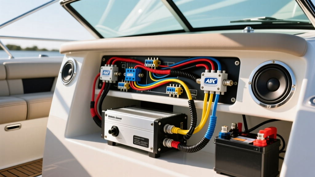
Upgrading Your Boat Audio: The Marine Environment Challenge
Upgrading the audio system on a center console or wakeboard boat is one of the most rewarding modification projects you can undertake. However, executing a reliable marine amp wiring diagram requires a fundamental shift in mindset from standard automotive installations. The marine environment is relentlessly hostile to electrical components. Saltwater, high humidity, constant UV exposure, and the relentless vibration of a planing hull will rapidly destroy standard car audio wiring. When you are adding high-output amplifiers to drive tower speakers and a subwoofer, the current draw is substantial. If your wiring is not up to the rigorous standards set by the American Boat and Yacht Council (ABYC), you risk catastrophic electrical fires, chronic voltage drop, and irreversible galvanic corrosion.
In this comprehensive upgrade guide, we will walk through the exact schematic, wire selection, and termination protocols required to install a multi-channel marine amplifier safely and effectively. Unlike a car, a boat does not have a steel chassis to serve as a ground return path. Every single negative wire must be routed back to a dedicated negative bus bar, making the marine amp wiring diagram inherently more complex and wire-intensive than its automotive counterpart.
ABYC E-11 Compliance: Wire Selection and Color Codes
The foundation of any marine audio upgrade is the wire itself. You must exclusively use marine-grade, tinned copper wire that meets UL 1426 or SAE J1128 specifications. The tinning process coats each individual copper strand in a microscopically thin layer of tin, which prevents the black copper oxide corrosion that chokes conductivity in standard oxygen-free copper (OFC) automotive wire. According to Marine How To, using untinned wire in a marine environment will result in terminal failure within a single season of saltwater exposure.
Marine DC Wire Color Code Reference
While aftermarket car audio harnesses use a universal color code (yellow for constant 12V, red for ignition, black for ground), marine DC wiring follows strict ABYC E-11 color codes to prevent dangerous cross-circuiting. When adapting your head unit and amplifier remote turn-on circuits, adhere to the following marine standards:
- DC Positive (Main Power): Yellow (or Yellow with a Red stripe)
- DC Negative (Ground Return): Black (or Yellow with a Black stripe)
- Ignition Switched (Accessory): Red (Note: ABYC prefers Yellow/Red for ignition, but Red is widely accepted in aftermarket marine stereo harness adaptations)
- Amplifier Remote Turn-On: Blue (Standardized across most marine head units and amplifiers)
Step-by-Step Marine Amp Wiring Diagram Execution
When routing wires for a center console upgrade, you are typically running cables from the battery compartment in the stern or under the leaning post, up through the helm rigging tube, and to the amplifier mounted under the dash or in a dedicated locker. Proper separation of power and signal is critical to avoid alternator whine, which is highly prevalent in marine charging systems.
Phase 1: Power Delivery and MRBF Fusing
Begin at the battery bank. Marine electrical codes dictate that the main overcurrent protection device must be installed within 7 inches of the battery positive terminal. For a high-current audio upgrade, an MRBF (Marine Rated Battery Fuse) mounted directly on the battery post is the gold standard. From the MRBF, route your main 4 AWG or 1/0 AWG yellow tinned power wire through the rigging tube. Use a fish tape and apply a wire-pulling lubricant to avoid snagging the steering cables or hydraulic lines. Secure the wire every 18 inches using UV-resistant cable clamps, ensuring the wire does not rest against sharp fiberglass edges or hot engine manifolds.
Phase 2: Signal Routing and Grounding to the Bus Bar
Run your marine-grade RCA cables and the blue remote turn-on wire on the opposite side of the rigging tube from the main power wire. If they must cross, ensure they intersect at a strict 90-degree angle to minimize electromagnetic interference (EMI). Because fiberglass hulls cannot conduct electricity, your amplifier's ground wire cannot be bolted to the hull or a seat bracket. You must route a black negative wire, equal in gauge to the positive power wire, all the way back to the main negative DC bus bar. This ensures a clean, low-resistance return path to the battery and prevents ground loops that cause severe alternator whine through your tower speakers.
Marine Amplifier AWG and Voltage Drop Specification Chart
Marine systems operate on a strict 3% maximum voltage drop rule for critical and high-draw circuits, as outlined by ABYC. Because the ground wire must be run all the way back to the battery bus bar (effectively doubling the total circuit length compared to a car), you must calculate your AWG size based on the total round-trip distance. Use the chart below to select the correct tinned copper wire gauge for your amplifier's maximum current draw.
| Total Circuit Length (Positive + Negative) | Max Current Draw (Amps) | Required Wire Gauge (AWG) | Recommended Fuse Size | Typical Application |
|---|---|---|---|---|
| Up to 15 feet | 60A | 8 AWG | 70A ANL | 4-Channel Tower Amp (400W) |
| Up to 20 feet | 100A | 4 AWG | 110A ANL | 5-Channel System Amp (800W) |
| Up to 25 feet | 150A | 2 AWG | 175A ANL | Multiple Amps / Subwoofer Amp |
| Up to 30 feet | 200A+ | 1/0 AWG | 250A Class T | High-Output Competition Wake Audio |
Note: Always install an inline ANL or Class T fuse within 18 inches of where the power wire connects to the amplifier or distribution block, in addition to the main MRBF fuse at the battery.
Termination Protocols: Crimping and Waterproofing
The most common point of failure in a marine amp wiring diagram is the termination point. Solder is strictly prohibited by ABYC as the sole method of connection because it is brittle and will crack under the harmonic vibration of a boat hull. You must use a mechanical crimp. According to JL Audio Marine Engineering guidelines, proper crimping ensures a gas-tight seal that prevents moisture ingress at the strand level.
For every connection at the amplifier, distribution block, and bus bar, follow this waterproofing protocol:
- Strip the tinned wire using a precision wire stripper to avoid nicking the outer strands.
- Slide a piece of 3:1 ratio, dual-wall adhesive-lined marine heat shrink onto the wire before crimping.
- Use a ratcheting hex-crimp tool to compress the tinned copper ring terminal. A ratcheting tool ensures the exact amount of pressure is applied, preventing cold crimps or crushed strands.
- Slide the adhesive heat shrink over the barrel of the terminal, ensuring it overlaps the wire insulation by at least half an inch.
- Apply heat evenly until the adhesive melts and squeezes out of the ends, creating a 100% waterproof, salt-resistant seal.
Diagnostic Troubleshooting: Common Marine Audio Faults
Even with a flawless marine amp wiring diagram, the harsh environment can introduce faults over time. Use this diagnostic tree to troubleshoot common marine audio electrical issues:
- Symptom: Amplifier goes into 'Protect' mode only when the engine is at high RPM or the boat is planing.
Cause: Voltage spikes from the marine alternator or severe voltage drop due to a corroded negative bus bar connection.
Fix: Inspect the negative bus bar for green copper chloride corrosion. Clean with a wire brush, apply dielectric grease, and verify the alternator output does not exceed 14.8V at high RPM. - Symptom: High-pitched alternator whine in the tower speakers that changes pitch with engine RPM.
Cause: Ground loop caused by running the RCA cables parallel to the main DC power wire, or the head unit and amplifier are grounded to different points with varying resistance.
Fix: Ensure both the head unit ground and the amplifier ground tie into the exact same negative bus bar. Verify RCA cables are routed on the opposite side of the helm rigging tube from the 4 AWG power wire. - Symptom: Amplifier turns on, but no audio output; remote turn-on LED is dim.
Cause: Voltage drop on the blue remote turn-on wire due to an undersized wire gauge over a long run (common in large center consoles).
Fix: Upgrade the remote turn-on wire from 18 AWG to 14 AWG, or install a 12V marine relay near the amplifier, triggered by the head unit's remote wire, to switch the main 12V power locally.
By adhering strictly to ABYC standards, utilizing tinned copper, and executing meticulous waterproof terminations, your marine audio upgrade will deliver concert-level sound on the water while remaining completely safe and reliable for years to come.