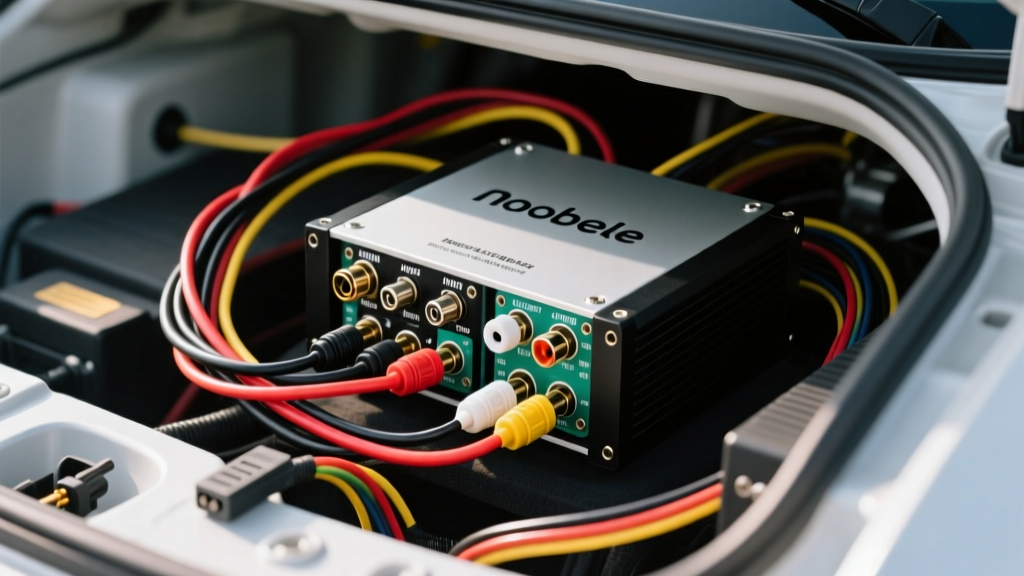
Understanding the Monoblock Architecture
When upgrading your vehicle's low-frequency response, a monoblock (single-channel) amplifier is the industry standard for driving subwoofers. Unlike multi-channel amplifiers that divide power across stereo speakers, a monoblock dedicates its entire power supply and Class D switching topology to a single output stage. This results in massive wattage output, high efficiency, and the ability to drive low-impedance loads (often down to 1 ohm). However, harnessing this power requires a precise monoblock amp wiring diagram to prevent voltage drops, thermal shutdowns, and alternator whine.
In this beginner-friendly guide, we will break down the fundamental wiring pathways, specify the exact American Wire Gauge (AWG) requirements, and outline the physical installation sequence to ensure your amplifier performs to its CTA-2006 compliant power ratings.
The Core Monoblock Amp Wiring Diagram Flow
A proper wiring diagram for a Class D monoblock amplifier consists of five distinct circuits: Main Power, Ground, Remote Turn-On, Signal Input (RCA), and Speaker Output. Let us dissect each pathway with exact specifications.
1. Main Power and Fuse Placement
The power circuit draws high current directly from the vehicle's positive battery terminal. For a typical 500W to 1000W RMS monoblock, you will need 4 AWG or 1/0 AWG Oxygen-Free Copper (OFC) wire.
- Fusing: An ANL or AGU fuse must be installed on the positive power wire within 18 inches of the battery's positive post. This protects the vehicle from catastrophic short circuits in the event of a collision or wire chafing.
- Routing: Run the power wire down the side of the vehicle opposite to your RCA signal cables to prevent electromagnetic interference (EMI).
- Termination: Use a closed-loop ring terminal, crimped with a hex-crimper, and sealed with adhesive-lined heat shrink to prevent moisture intrusion and copper oxidation.
2. The Critical Ground Connection
The ground wire completes the circuit and is the number one cause of amplifier failure and audio noise when executed poorly. The ground wire must be the exact same AWG as your power wire and should never exceed 18 inches in length.
- Chassis Prep: Locate a thick, structural metal point on the vehicle's chassis or floor pan. Use 80-grit sandpaper or a wire wheel to remove all paint, primer, and rust down to bare, shiny steel.
- Hardware: Secure the ring terminal using a 5/16-inch or 3/8-inch zinc-plated or stainless steel bolt, flat washer, split lock washer, and a nut with a Nyloc insert. Torque to approximately 5-7 Nm to ensure a gas-tight connection.
- Corrosion Protection: After tightening, coat the exposed bare metal and terminal in dielectric grease or clear nail polish to prevent future rust.
3. Remote Turn-On (REM) and RCA Signal Routing
The remote turn-on circuit signals the amplifier to power up its internal switching supply.
- Wire Spec: Use 18 AWG stranded wire. Connect one end to the head unit's remote output (typically a blue wire with a white stripe) and the other to the amp's "REM" terminal.
- RCA Cables: Use heavily shielded, twisted-pair RCA interconnects. The RCA pinout consists of the Tip (positive signal) and the Sleeve (signal ground). Keep these cables routed through the center console or opposite kick panel, far away from the main power wire.
4. Subwoofer Output and Impedance Matching
Monoblocks do not have left and right channels; they have positive and negative speaker terminals designed to handle massive current. Use 12 AWG to 14 AWG speaker wire. Ensure your subwoofer's final impedance matches the amplifier's stable rating (e.g., wiring two dual 4-ohm voice coil subwoofers in parallel to present a 1-ohm load to a 1-ohm stable monoblock).
Essential Wiring Specification Chart
Choosing the wrong wire gauge leads to voltage drop, which starves the amplifier and triggers "protect" mode. The following chart is based on SAE J1128 standards for OFC (Oxygen-Free Copper) wire at a standard 14.4V automotive charging system with a maximum allowable 0.5V drop.
| Max Amplifier Draw (Amps) | Wire Gauge (OFC) | Max Cable Length (Under 10 ft) | Max Cable Length (10-16 ft) | Recommended Fuse Size |
|---|---|---|---|---|
| 0 - 35A | 8 AWG | 12 ft | 8 ft | 40A |
| 35 - 65A | 4 AWG | 14 ft | 10 ft | 70A |
| 65 - 100A | 2 AWG | 16 ft | 12 ft | 120A |
| 100 - 150A | 1/0 AWG | 18 ft | 14 ft | 175A |
| 150 - 200A+ | 2/0 AWG | 20 ft | 16 ft | 225A |
Note: If you are using CCA (Copper-Clad Aluminum) wire, you must step up one full gauge size (e.g., use 2 AWG CCA instead of 4 AWG OFC) due to aluminum's higher electrical resistance.
Step-by-Step Installation Sequence
Follow this exact sequence to prevent short circuits and ensure a clean signal path:
- Disconnect the Battery: Always remove the negative (-) battery terminal first and isolate it before running any wires.
- Mount the Amplifier: Secure the amp to a non-conductive surface or ensure it is isolated from the chassis if mounting to metal. Ensure at least 2 inches of clearance around the heat sink fins for convection cooling.
- Run the Power Wire: Route the main power cable through the firewall using an existing rubber grommet. Pierce the grommet carefully, run the wire, and seal the hole with silicone.
- Install the Fuse Holder: Crimp and mount the fuse holder within 18 inches of the battery. Do not insert the fuse yet.
- Run Signal and Remote Wires: Route the RCA cables and 18 AWG remote wire down the opposite side of the vehicle's interior.
- Make Amplifier Connections: Strip exactly 3/8-inch of insulation from your power, ground, and speaker wires. Insert them into the amplifier's set-screw terminals and tighten firmly. Give each wire a gentle tug to ensure it is seated.
- Establish Ground: Sand the chassis, bolt down the ground ring terminal, and apply corrosion protection.
- Finalize Power: Reconnect the vehicle's negative battery terminal. Insert the main fuse into the engine bay fuse holder.
Real-World Troubleshooting & Failure Modes
Even with a perfect diagram, real-world variables can cause issues. Here is how to diagnose common monoblock failures using a digital multimeter (DMM):
Symptom: Alternator Whine (High-Pitched Noise)
Cause: Ground loop or RCA shield interference. The amplifier is picking up the vehicle's charging system noise because the RCA ground and the amplifier chassis ground are at different electrical potentials.
Fix: First, verify your RCA cables are not routed parallel to the power wire. Second, check the amplifier ground. Measure the voltage drop between the amplifier's ground terminal and the negative battery post with the engine running and the volume up. If the reading exceeds 0.05V, your ground is inadequate. Re-sand the chassis point.
Symptom: Amplifier Goes into "Protect" Mode at High Volume
Cause: Voltage drop on the power wire or impedance mismatch.
Fix: Measure the DC voltage at the amplifier's B+ and GND terminals while playing heavy bass tracks at high volume. If the voltage drops below 11.5V, your power wire is too thin, your battery is weak, or you have a poor ground. If voltage remains above 12.5V, use your DMM's ohmmeter function to measure the subwoofer's impedance at the amp terminals. If the impedance is lower than the amp's rated stability (e.g., measuring 0.6 ohms on a 1-ohm stable amp), the amplifier is engaging its short-circuit protection to prevent internal MOSFET failure.
Symptom: Amplifier Does Not Turn On
Cause: Loss of Remote Turn-On voltage.
Fix: Set your DMM to DC Voltage. Place the red probe on the amplifier's REM terminal and the black probe on the GND terminal. Turn on the head unit. You should read between 12V and 14.4V. If you read 0V, trace the 18 AWG remote wire back to the head unit. If you read voltage but the amp stays off, check the main power fuse and verify 12V+ at the main B+ terminal.
Final Thoughts on Car Audio Wiring
Building a reliable subwoofer system is less about the brand of the amplifier and more about the integrity of the installation. By strictly following this monoblock amp wiring diagram, utilizing OFC cabling, and adhering to proper termination techniques, you ensure that your amplifier receives the clean, uninterrupted current it needs to reproduce low frequencies with absolute authority. Always prioritize safety, double-check your impedance math, and take the time to prep your ground connections properly.