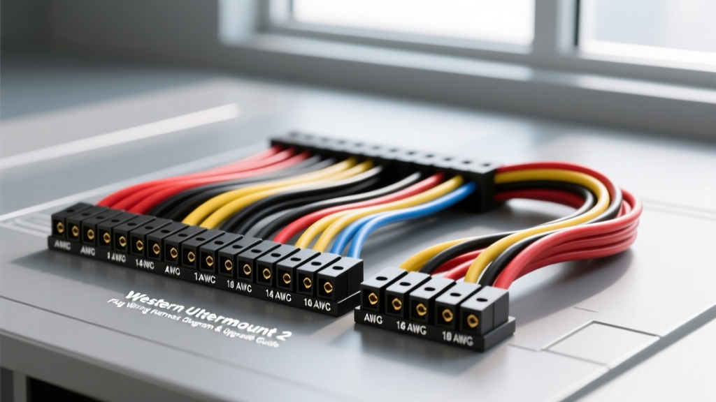
Introduction to the Ultramount 2-Plug Upgrade
Upgrading a truck’s snow plow electrical system from an aging 3-plug setup to the modern Western Ultramount 2-plug configuration is one of the most reliable modifications you can perform for winter operations. The Western Ultramount 2 plug wiring harness diagram simplifies the connection between the truck-side harness and the plow-side assembly, reducing failure points and improving voltage delivery to the hydraulic motor and lighting circuits. Whether you are converting an older fleet truck or fabricating a custom harness for a new rig, understanding the exact pinouts, AWG requirements, and connector specifications is critical for a safe, high-performance installation.
Why Upgrade to the Ultramount 2-Plug System?
Older Western systems utilized a 3-plug design: separate connectors for the hydraulic motor power, the control circuit, and the lighting. This multi-connector approach was prone to moisture ingress, pin corrosion, and excessive voltage drop across multiple junction points. The Ultramount 2-plug system consolidates these into two robust connections:
- The 2-Pin High-Current Power Connector: Dedicated solely to the hydraulic motor's heavy amperage draw and main ground.
- The 13-Pin Control and Lighting Connector: Handles all multiplexed control signals, lighting circuits, and low-amperage grounds.
By isolating the high-amperage motor circuit from the sensitive control and lighting circuits, the 2-plug system drastically reduces electromagnetic interference (EMI) and prevents voltage drops that cause solenoid chatter or dim plow lights.
Western Ultramount 2 Plug Wiring Harness Diagram Breakdown
The 2-Pin High-Current Power Connector (Motor & Ground)
The 2-pin connector is the backbone of the plow's hydraulic power. It typically utilizes a heavy-duty weatherpack or an Anderson SB175-style connector (such as the Western 79730 or equivalent). Because the hydraulic motor can draw upwards of 150 to 200 amps under heavy load (e.g., when pushing a heavy, wet snowbank), the wire gauge and crimp quality are paramount.
- Pin A (Power): Red wire, SAE J1128 compliant 2 AWG or 4 AWG Oxygen-Free Copper (OFC). This runs from the truck-side solenoid to the plow-side motor positive terminal.
- Pin B (Ground): Black wire, 2 AWG or 4 AWG OFC. This provides the main return path to the chassis or battery negative.
Expert Modification Tip: Many factory truck-side harnesses use 4 AWG wire. When performing an upgrade project, we strongly recommend upgrading the main battery-to-solenoid feed and the solenoid-to-plug feed to 2 AWG or 1/0 AWG wire. This mitigates voltage drop over long wheelbase trucks (like crew-cab duallys) and ensures the motor receives a full 12.6V under load.
The 13-Pin Control and Lighting Connector
The 13-pin connector (often referred to as the Fleetmaster or Multiplex plug) handles all auxiliary functions. The pins are lettered A through M (skipping I and O to prevent confusion with numbers 1 and 0). The wires in this harness are typically 14 AWG for grounds and ignition feeds, and 16 AWG for signal and lighting circuits.
13-Pin Control Connector Pinout Specification Table
| Pin | Wire Color | Function | AWG Size | Circuit Notes |
|---|---|---|---|---|
| A | Black | Chassis Ground | 14 AWG | Main control ground return. |
| B | Red | 12V Ignition Feed | 14 AWG | Switched power from truck cab. |
| C | White | Left Turn Signal | 16 AWG | Syncs with truck left turn. |
| D | Brown | Running/Tail Lights | 16 AWG | Plow marker and tail lights. |
| E | Green | Right Turn Signal | 16 AWG | Syncs with truck right turn. |
| F | Blue | High Beam Headlights | 16 AWG | Plow high beam trigger. |
| G | Black | Lighting Ground | 14 AWG | Dedicated ground for lighting. |
| H | Yellow | Motor Up | 16 AWG | Valve coil trigger (Raise). |
| J | Orange | Motor Down | 16 AWG | Valve coil trigger (Lower). |
| K | Purple | Motor Left | 16 AWG | Valve coil trigger (Angle Left). |
| L | Dark Blue | Motor Right | 16 AWG | Valve coil trigger (Angle Right). |
| M | Light Green | Auxiliary / Plow Lights | 16 AWG | Work lights or low beam trigger. |
Step-by-Step Truck-Side Harness Modification
When fabricating or upgrading the truck-side portion of the Western Ultramount 2 plug wiring harness, follow these professional-grade steps to ensure longevity and reliability in harsh, salt-heavy winter environments.
- Disconnect and Isolate Power: Remove the negative battery cable. Secure it away from the terminal to prevent accidental arcing.
- Upgrade the Main Power Feed: Remove the factory 4 AWG power cable running from the battery to the plow solenoid. Fabricate a new cable using 2 AWG OFC wire. Use a heavy-duty hex-crimp tool to attach 3/8" ring terminals. Seal the crimp joints with dual-wall, adhesive-lined heat shrink to prevent capillary action from drawing moisture into the copper strands.
- Install a High-Amp Mega Fuse: Install a 175A or 200A Mega Fuse within 18 inches of the battery positive terminal. This protects the main 2 AWG feed in the event of a dead short against the chassis.
- Route the 13-Pin Harness: Route the 13-pin control harness away from high-heat sources (exhaust manifolds, turbochargers). Secure it with UV-resistant zip ties every 12 inches. Use split-loom tubing where the harness passes through the firewall or near sharp chassis brackets.
- Torque Specifications: When terminating the 2 AWG power cables at the solenoid studs and battery terminals, torque the hardware to 12-15 ft-lbs. Overtightening can strip the aluminum threads on the solenoid mounting plate, while undertightening will cause micro-arcing and severe heat buildup.
- Apply Dielectric Compound: Before mating the 2-pin and 13-pin connectors, pack the pin cavities with a lithium-based dielectric grease (such as Nyogel 760G). This displaces moisture and prevents galvanic corrosion between the brass pins and the environmental salt.
Common Voltage Drop Issues and Troubleshooting
Even with a perfect Western Snow Plows wiring diagram, real-world conditions can introduce faults. Use this diagnostic decision tree to troubleshoot common Ultramount 2-plug issues.
Symptom: Solenoid Clicks Rapidly (Chatter) but Motor Doesn't Run
- Cause 1: Severe Voltage Drop on Pin A (Power). Fix: Use a digital multimeter (DMM) to measure voltage at the solenoid output terminal while the control switch is engaged. If voltage drops below 10.5V, the 2 AWG cable is degraded, or the crimp is failing. Replace the cable.
- Cause 2: Poor Ground on Pin B. Fix: The plow-side ground strap connecting the motor housing to the truck chassis is often corroded. Remove the ground bolt, clean the mating surface down to bare metal with a wire wheel, apply anti-seize, and re-torque.
Symptom: Plow Lights Flicker or Dim When Angling the Blade
- Cause: Shared Ground Overload on Pin G. Fix: The hydraulic valve coils draw a momentary spike of 5-8 amps each when engaged. If the 14 AWG ground on Pin G is compromised, the current will backfeed through the lighting ground, causing flicker. Verify continuity from Pin G to the truck chassis. If resistance is above 0.5 ohms, run a dedicated 12 AWG bypass ground wire directly from the plow light harness to the truck battery negative.
Symptom: Control Module Fails to Power On
- Cause: Blown Ignition Feed Fuse on Pin B. Fix: Check the 10A or 15A inline fuse on the Red (Pin B) ignition wire in the cab. If the fuse is intact, test for 12V at the truck-side 13-pin connector Pin B with the ignition in the 'Run' position. A lack of voltage indicates a broken wire inside the firewall grommet, a common failure point due to repeated steering shaft friction.
Authoritative References & Standards
When designing or modifying heavy-duty automotive electrical systems, always adhere to established engineering standards. For wire gauge selection and insulation ratings, refer to the SAE J1128 Low Tension Primary Cable Standard. For specific OEM pinout updates, relay logic, and multiplex module programming, always consult the latest Western Snow Plows Official Literature and eLearning Modules. Proper adherence to these guidelines ensures your Ultramount 2-plug upgrade will withstand the harshest winter conditions without electrical failure.