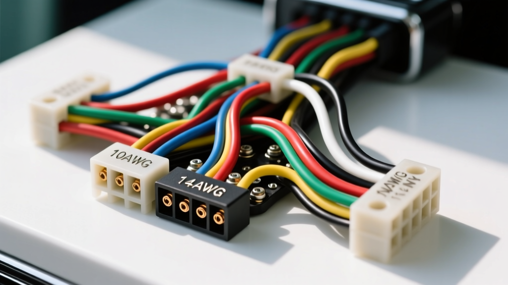
1964 Chevrolet Impala Electrical Architecture Overview
The 1964 Chevrolet Impala represents a critical transition era in American automotive electrical design. As the final model year utilizing the iconic cruciform X-frame chassis before the shift to the perimeter frame in 1965, the 1964 Impala wiring harness features unique routing pathways, specific firewall pass-through configurations, and a heavy reliance on external voltage regulation for its standard Delco-Remy generator systems. Understanding the exact specifications, AWG ratings, and factory color codes is essential for anyone performing a restoration, troubleshooting a parasitic draw, or installing a modern aftermarket harness kit.
Unlike later models that utilized a single, sealed bulkhead connector block, the 1964 Chevrolet full-size passenger cars routed the main engine bay harness through a large, reinforced rubber cowl grommet on the driver-side firewall. This design requires meticulous attention to grommet seating and wire loom wrapping to prevent chafing against the steel firewall edge, a common failure point that leads to dead shorts in the primary 10 AWG battery feed circuits.
X-Frame Routing and Chassis Grounding Specifications
The 1964 Impala X-frame dictates the physical layout of the underbody and rear lighting harness. The main harness branches at the firewall junction block, with the rear body harness routing down the left-side frame rail. Factory specifications call for the harness to be secured every 12 to 14 inches using steel retaining clips with integrated neoprene cushions.
Because the X-frame relies heavily on the body-to-frame bonding for electrical continuity, the 1964 Impala requires dedicated ground straps. The primary engine-to-frame ground is a heavy-duty 4 AWG braided copper strap located near the right-side motor mount. A secondary 10 AWG ground wire routes from the engine block to the firewall. When restoring or replacing the 1964 Impala wiring harness, failing to reinstall these dedicated ground straps will result in voltage drops across the headlight circuits and erratic behavior in the fuel gauge, as the instruments attempt to ground through the throttle linkage and speedometer cable.
Primary Wire Color Codes and AWG Ratings
The factory utilized color-coded PVC-insulated copper wire conforming to early iterations of the SAE J1128 Low Tension Primary Cable Standard. When sourcing replacement wire or verifying an existing harness, cross-reference the following factory color and gauge specifications:
| Circuit Function | Factory Wire Color | AWG Size | Routing Path |
|---|---|---|---|
| Main Battery Feed (Horn Relay to Firewall) | Red | 10 AWG | Engine bay, driver side |
| Ignition Switch 'ON' Feed to Fuse Box | Pink | 12 AWG | Through cowl grommet to dash |
| Starter Solenoid 'S' Terminal Feed | Purple | 12 AWG | Engine bay, routed away from exhaust |
| Headlight Feed from Dimmer Switch | Red | 12 AWG | Driver side inner fender |
| Low Beam Headlight Feed | Green | 12 AWG | Front core support |
| High Beam Headlight Feed | Blue | 12 AWG | Front core support |
| Taillight and Parking Light Feed | Brown | 14 AWG | Left frame rail to rear body |
| Right Rear Stop/Turn Signal | Dark Green | 14 AWG | Left frame rail, crosses to right at rear |
| Left Rear Stop/Turn Signal | Yellow | 14 AWG | Left frame rail to left rear quarter |
| Fuel Gauge Sender Feed | Tan | 18 AWG | Left frame rail to fuel tank |
Headlight and Dimmer Switch Circuit Topology
The 1964 Impala headlight circuit is protected by an internal thermal circuit breaker located within the headlight switch assembly on the dashboard, rather than a standard glass-tube fuse. The main 12 AWG Red wire feeds from the horn relay bus bar directly to the headlight switch. From the switch, a 12 AWG Red wire routes to the floor-mounted 3-terminal dimmer switch.
The dimmer switch distributes power to the front core support. A frequent diagnostic error occurs when restorers miswire the dimmer switch terminals. The correct factory configuration is:
- Terminal 1 (Input): 12 AWG Red (from headlight switch)
- Terminal 2 (Output): 12 AWG Green (Low Beams)
- Terminal 3 (Output): 12 AWG Blue (High Beams and Dashboard Indicator)
When upgrading to modern halogen or LED sealed beam replacements, the increased current draw or the lack of resistance in LEDs can cause the factory thermal breaker to trip prematurely. If upgrading lighting, it is highly recommended to install a headlight relay kit, using the factory 12 AWG Green and Blue wires merely as low-current trigger signals for the relay coils.
External Voltage Regulator (Generator) Pinout
While the 1965 model year introduced the internally regulated Delco 10SI alternator as standard equipment, the 1964 Impala predominantly utilized a Delco-Remy generator paired with a 4-terminal external voltage regulator mounted on the radiator support. Understanding this specific harness branch is critical, as many salvage-yard 1964 harnesses have been hacked to accommodate later alternator swaps.
The factory harness connector for the external regulator features four distinct circuits. According to the Classic Industries 1964 Chevrolet Assembly Manual, the pinout and wire colors are as follows:
| Regulator Terminal | Wire Color | AWG | Destination / Function |
|---|---|---|---|
| BAT (Battery) | Red | 10 AWG | Horn Relay Bus Bar (Main Power Sense) |
| ARM (Armature) | Blue | 14 AWG | Generator ARM terminal |
| GEN (Generator) | White | 14 AWG | Generator Output / Ammeter Sense |
| FLD (Field) | Green | 14 AWG | Generator FLD terminal |
Diagnostic Note: If the ammeter shows a constant discharge at highway speeds, check the 14 AWG Green Field wire for continuity. A break in this wire prevents the regulator from energizing the generator's field coils, resulting in zero charging output despite a healthy generator and battery.
Common Degradation and Failure Modes in Original Harnesses
Original 1964 Impala wiring harnesses are now over half a century old. The PVC insulation used in the 1960s becomes brittle when exposed to decades of under-hood thermal cycling and UV radiation. When evaluating an original harness, inspect the following high-failure areas:
- Exhaust Manifold Proximity: The 12 AWG Purple starter feed and the 14 AWG generator wires route dangerously close to the right-side exhaust manifold on 283 and 327 cubic inch V8 engines. Melted insulation here causes a direct short to the block, often resulting in a melted ignition switch.
- Steering Column Dash Harness: The harness wrapping behind the instrument cluster is subjected to extreme heat from the factory heater core box. The 18 AWG Tan (fuel gauge) and 18 AWG Dark Green (temperature gauge) wires frequently crack, leading to pegged or dead gauges.
- Trunk Lid Flex Loom: The rear harness passes into the trunk lid via a flexible rubber conduit. Repeated opening and closing fatigues the 14 AWG Brown taillight wire and the 18 AWG license plate lamp wire, causing intermittent rear lighting failures.
Modern Replacement Harness Upgrades and Considerations
When sourcing a replacement 1964 Impala wiring harness, premium manufacturers like those documented in American Autowire Classic Update Harness Documentation utilize modern GXL or TXL cross-linked polyethylene insulation. TXL wire features a significantly thinner insulation wall while maintaining a higher temperature rating (up to 125°C compared to the original PVC's 85°C). This allows for easier routing through the tight cowl grommet and provides superior resistance to under-hood heat and automotive fluids.
Furthermore, modern replacement kits often integrate a centralized ATO/ATC blade fuse block in place of the factory glass-tube fuse block. If utilizing a modern harness, ensure that the main power feed from the battery to the new fuse block utilizes at least 8 AWG or 6 AWG wire, as modern aftermarket accessory loads (electric cooling fans, high-output fuel pumps, and digital ignitions) far exceed the 40-amp total capacity of the original 1964 generator system. Always pair a modern harness upgrade with a high-output 1-wire or 3-wire alternator conversion to ensure adequate amperage delivery at idle.