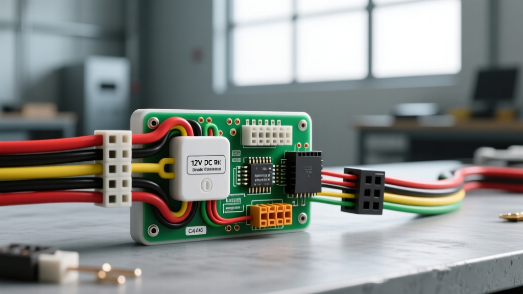
Understanding the 12V DC Smoke Alarm Harness Architecture
In recreational vehicles, motorhomes, and commercial fleet applications, life safety systems are governed by strict electrical standards. Unlike residential 120V AC systems, an RV relies on a 12V DC smoke alarm wiring harness to power and interconnect carbon monoxide and smoke detectors. According to the NFPA 1192 Standard on Recreational Vehicles, hardwired, interconnected alarms are mandatory for motorized RVs to ensure that a fire in the rear bedroom triggers the alarm in the front cab.
Troubleshooting these low-voltage harnesses requires a systematic approach. Voltage drop, parasitic draws, and interconnect signal failures are the most common issues. This guide provides a step-by-step diagnostic flow to isolate faults within the harness, connectors, and alarm heads.
Standard 3-Wire Harness Specification Chart
Most modern OEM RV smoke alarm harnesses utilize a 3-cavity Delphi Packard Metri-Pack 150 or Molex Mini-Fit Jr. connector. The wire gauge is typically dictated by SAE J1128 standards for low-voltage primary cable.
| Pin / Cavity | Wire Color | AWG Size | Circuit Function | Voltage Expectation |
|---|---|---|---|---|
| Pin 1 (A) | Red | 16 AWG | 12V Constant Power (Fused 5A-10A) | 12.0V - 13.8V DC |
| Pin 2 (B) | White | 16 AWG | Chassis Ground | < 0.05V Drop |
| Pin 3 (C) | Yellow / Orange | 18 AWG | Interconnect Signal (Daisy Chain) | 0V (Standby) / 9V-12V (Active) |
Symptom-to-Cause Decision Tree
Before unclipping the harness connector, identify the primary symptom to determine your diagnostic starting point. Use this decision tree to narrow down the failure mode.
- Symptom A: Constant 'Low Battery' Chirping (Despite Full House Batteries)
- Cause 1: Severe voltage drop across the 16 AWG Red power wire or corroded Pin 1 terminal.
- Cause 2: High resistance on the 16 AWG White ground circuit causing a floating ground.
- Fix Path: Proceed to Phase 2, Step 1 (Voltage Drop Test).
- Symptom B: Interconnect Failure (One Alarm Triggers, Others Remain Silent)
- Cause 1: Open circuit in the 18 AWG Yellow/Orange interconnect wire between the triggering node and the silent node.
- Cause 2: Backed-out terminal in the Metri-Pack connector at the daisy-chain junction.
- Fix Path: Proceed to Phase 2, Step 3 (Interconnect Continuity).
- Symptom C: False Alarms / Nuisance Tripping (No Smoke Present)
- Cause 1: The 18 AWG interconnect wire is chafing and intermittently shorting to the 12V Red power wire.
- Cause 2: Galvanic corrosion inside the harness connector causing cross-circuit leakage.
- Fix Path: Inspect harness routing near HVAC ducts and sharp metal bulkheads.
- Symptom D: Parasitic Battery Drain (RV Batteries Dead After Storage)
- Cause 1: Failed capacitor inside the alarm head drawing excess current.
- Cause 2: Harness insulation breakdown causing a micro-short to the chassis.
- Fix Path: Proceed to Phase 2, Step 4 (Parasitic Draw Isolation).
Phase 2: Step-by-Step Multimeter Diagnostic Flow
Set your digital multimeter (DMM) to the appropriate settings. Do not rely on simple test lights, as they do not reveal the micro-voltage drops that trigger false low-battery warnings in sensitive CMOS alarm circuitry.
Step 1: The Voltage Drop Test (Power & Ground)
A smoke alarm head will trigger a low-battery chirp if the input voltage drops below 10.2V. If your RV house battery bank reads 12.8V, but the alarm is chirping, you have a harness voltage drop issue.
- Set your DMM to DC Millivolts (mV).
- Leave the harness connected to the alarm head and the distribution block.
- Place the positive probe on the 12V source terminal at the fuse block, and the negative probe on Pin 1 (Red wire) at the back of the alarm connector.
- Read the drop. A healthy 16 AWG circuit should show less than 50mV (0.05V) drop. If you read >200mV, the Red wire is undersized, damaged, or the fuse holder is corroded.
- Repeat for the ground circuit: Positive probe on Pin 2 (White wire) at the alarm, negative probe on a known clean chassis ground. A drop >50mV indicates a poor ground ring terminal crimp or chassis rust.
Step 2: Interconnect Signal Verification
The interconnect line (Pin 3) carries a DC voltage pulse (usually 9V to 12V) from the triggering alarm to the others. If the wire is shorted to ground, the system may fail to propagate the alarm.
- Set the DMM to DC Volts.
- Back-probe the Yellow/Orange wire at Pin 3 of the primary alarm.
- Press the 'Test' button on the primary alarm.
- The DMM should read a steady 9V-12V pulse. If it reads 0V, the internal relay of the alarm head has failed, or the wire is severed immediately at the terminal crimp.
- Move to the next alarm in the daisy chain and back-probe its Pin 3. If voltage is absent here but present at the previous node, you have an open circuit in the 18 AWG yellow wire between the two units.
Step 3: Parasitic Draw Isolation
If your RV batteries are draining during storage, the smoke alarm circuit is a prime suspect. A standard hardwired alarm draws roughly 30µA to 50µA in standby.
- Set the DMM to the 10A or µA setting (use the µA port for precision).
- Disconnect the smoke alarm harness at the main distribution block or fuse panel.
- Connect the DMM in series between the positive battery cable and the harness power feed.
- Wait 15 minutes for the alarm's internal capacitors to settle.
- If the draw reads above 2mA (2000µA), the harness has a short to ground, or the connected alarm heads have failed internal components. Unplug each alarm head one by one until the draw drops to isolate the faulty component.
Phase 3: Harness Repair and Connector Replacement
When the diagnostic flow points to a physical harness failure, proper repair techniques are mandatory to prevent future fires or system failures. Never use twist-on wire connectors or electrical tape in an RV environment, as vibration and thermal cycling will cause them to fail.
Terminal and Connector Repair
If the Delphi Metri-Pack 150 terminals are corroded or the locking tangs are broken, you must replace the pigtails.
- Stripping: Use a precision wire stripper to remove exactly 5mm of insulation from the 16 AWG and 18 AWG wires. Do not nick the copper strands.
- Crimping: Use a ratcheting crimp tool specifically calibrated for Metri-Pack 150 terminals. The crimp must secure both the conductor and the wire insulation tab. Perform a pull-test; a proper 16 AWG crimp should withstand over 40 lbs of tensile force.
- Sealing: Apply a small amount of dielectric grease to the terminal before inserting it into the plastic connector housing until you hear the retaining tang 'click'.
Splicing and Routing Best Practices
If you must splice a damaged section of the 18 AWG interconnect wire, use an adhesive-lined marine-grade heat shrink butt connector. The internal adhesive will melt and seal the connection against humidity and off-gassing from RV adhesives. Route the harness away from high-heat sources like water heater exhaust flues and sharp sheet metal bulkheads, utilizing split-loom tubing and P-clips secured with stainless steel screws.
Conclusion
A reliable smoke alarm wiring harness is critical for life safety in motorhomes and commercial vehicles. By understanding the 3-wire architecture, utilizing a multimeter for voltage drop and parasitic draw testing, and adhering to strict crimping standards, you can eliminate false alarms and ensure your interconnected system functions exactly as engineered. Always consult the specific OEM wiring schematic for your chassis manufacturer before modifying any life-safety circuits.