Introduction to PSI Sensor Harness Integration
When building a custom fuel system or upgrading to an aftermarket engine management system, understanding your psi wiring harness diagram is a critical fundamental. In automotive electronics, 'PSI' refers to the Pounds per Square Inch pressure sensors used to monitor fuel rail pressure, boost pressure, or oil pressure. These sensors translate hydraulic force into an analog voltage signal that the Engine Control Unit (ECU) uses to calculate injector pulse width and manage fuel trims. For beginners, navigating the pinouts, wire gauges, and shielding requirements of a pressure sensor harness can seem daunting. However, by breaking down the 3-wire circuit architecture, you can fabricate a reliable, noise-free harness that ensures accurate data logging and optimal engine performance.
Decoding the 3-Wire PSI Wiring Harness Diagram
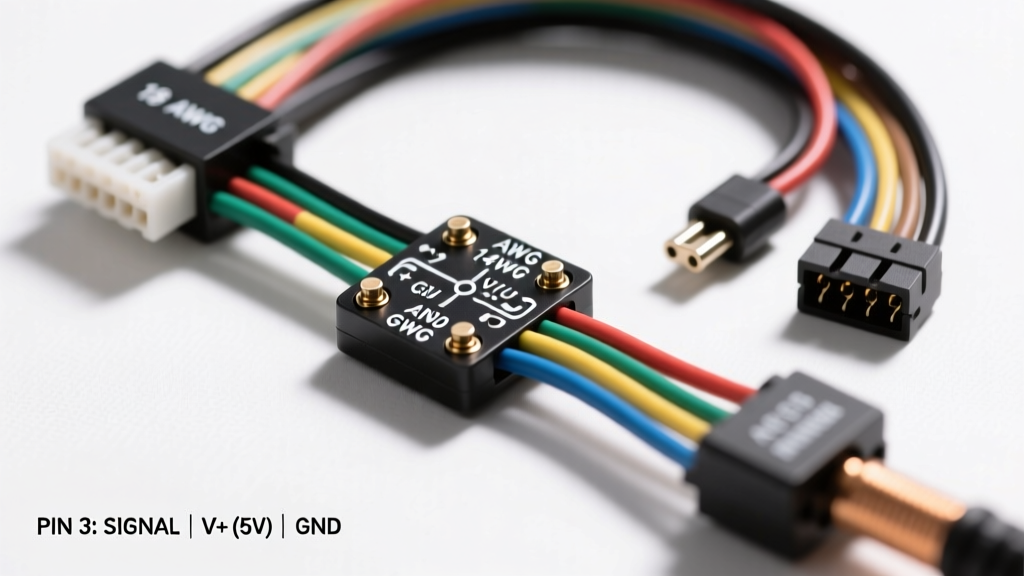
Modern automotive PSI sensors utilize a Wheatstone bridge internal circuit that requires three distinct connections to operate. Unlike older 1-wire or 2-wire variable resistance sensors, the 3-wire active design provides a linear 0-5V output that is highly resistant to voltage drop over long harness runs. Below is the standard pinout configuration used by major manufacturers like Holley, AEM, and Bosch.
| Pin / Cavity | Function | Typical Wire Color | Recommended AWG | ECU Header Connection |
|---|---|---|---|---|
| Pin A | 5V Reference (VREF) | Red or Orange | 20 AWG | Sensor 5V Reference Bus |
| Pin B | Sensor Ground | Black or White/Black | 20 AWG | Analog Sensor Ground |
| Pin C | Signal Output | Green or Blue | 22 AWG (Shielded) | Analog Input (e.g., Pin 24) |
Wire Gauge Selection and Harness Routing
Selecting the correct American Wire Gauge (AWG) is vital for maintaining signal integrity. While it might be tempting to use thick 16 AWG wire for the entire harness, doing so makes the harness stiff, difficult to route through the firewall, and prone to terminal back-out due to vibration. For the 5V Reference and Sensor Ground circuits, 20 AWG stranded copper wire is the industry standard. This gauge provides more than enough current-carrying capacity for the milliamp-level draw of a PSI sensor while remaining flexible.
The Importance of Shielded Twisted Pair (STP)
The Signal Output wire (Pin C) carries a low-voltage analog signal (typically 0.5V to 4.5V). This makes it highly susceptible to Electromagnetic Interference (EMI) generated by high-output ignition systems, such as MSD CDI boxes or Coil-Near-Plug (CNP) setups. To prevent the ECU from reading phantom pressure spikes, the signal wire must be routed using a Shielded Twisted Pair (STP) cable. The shielding acts as a Faraday cage, absorbing EMI and routing it to the ground. According to SAE J1113 standards for electromagnetic compatibility, the drain wire of the shielded cable must only be grounded at the ECU end. Grounding the shield at both the sensor and the ECU creates a ground loop, which will actually introduce alternator whine and ignition noise directly into your 5V signal.
Step-by-Step Harness Fabrication and Pinning
Creating a professional-grade harness requires the right connectors and crimping techniques. For PSI sensors located in the engine bay, environmental sealing is non-negotiable. The Deutsch DT series (3-way) or Weather-Pack connectors are the preferred choices due to their silicone secondary locks and rubber cavity plugs.
- Strip the Wire: Use a precision wire stripper to remove exactly 3mm of insulation from your 20 AWG and 22 AWG wires. Do not nick the copper strands, as this creates a stress riser that will snap under engine vibration.
- Crimp the Terminals: Use a ratcheting crimp tool calibrated for Deutsch DT contacts. The conductor crimp should fully encase the bare wire, while the insulation grip should securely hold the wire jacket. A proper 20 AWG crimp should withstand approximately 15 lbs of pull force without failing.
- Insert and Seal: Push the crimped terminals into the connector housing until you hear an audible 'click'. Insert the appropriate silicone cavity plugs into any unused holes to maintain the IP67 waterproof rating.
- Terminate the Shield: Strip back the foil shield and drain wire on the signal cable. Solder the drain wire to a dedicated ground pin on the ECU header, ensuring it does not share a ground path with high-current devices like fuel pump relays.
Calibrating the PSI Transfer Function in the ECU
Once your psi wiring harness diagram is physically executed, the ECU must be programmed to interpret the voltage. Most standard 100 PSI fuel pressure sensors utilize a linear transfer function. At 0 PSI, the sensor outputs 0.5V. At 100 PSI, it outputs 4.5V. The mathematical formula programmed into the ECU's sensor calibration table is: Pressure = (Voltage - 0.5) * 25. If your ECU reads 2.5V at idle, the math dictates (2.5 - 0.5) * 25 = 50 PSI. Always verify this baseline with a mechanical analog gauge on the fuel rail before relying on the electronic sensor for closed-loop fuel control. For specific ECU pinouts and calibration tables, refer to the Holley EFI Wiring Manual or AEM Infinity documentation.
Multimeter Diagnostics: Troubleshooting the PSI Circuit
When your datalog shows erratic fuel pressure or the ECU throws a 'Sensor Out of Range' fault, use a digital multimeter (DMM) to diagnose the harness. Never pierce the wire insulation with a test light or probe; this introduces corrosion and ruins the shielded cable. Instead, back-probe the connector while it is mated to the sensor.
| Symptom | Probable Cause | Diagnostic Step & Fix |
|---|---|---|
| ECU reads exactly 0.0 PSI or 5.0V | Open circuit on Signal Wire (Pin C) | Check for continuity between Sensor Pin C and ECU Analog Input. Repair broken wire or re-crimp terminal. |
| ECU reads erratic, jumping values | EMI Interference or Ground Loop | Verify shield drain wire is grounded ONLY at the ECU. Reroute harness away from ignition coils and alternator. |
| ECU reads 4.8V regardless of pressure | Short to 5V Reference or Open Ground | Measure resistance between Pin B (Ground) and engine block. Should be less than 0.5 ohms. Fix ground connection. |
| ECU reads 0.1V regardless of pressure | Short to Ground on Signal Wire | Disconnect ECU and Sensor. Check continuity between Signal Wire and chassis ground. Repair pinched harness. |
Summary
Mastering the fundamentals of a psi wiring harness diagram bridges the gap between a frustrating electrical gremlin and a reliable, data-rich fuel system. By adhering to proper AWG sizing, utilizing shielded twisted pair cabling for the signal return, and executing moisture-sealed crimps, you ensure that your ECU receives the pristine data required to keep your engine running safely under all load conditions.