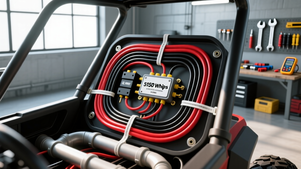
Why UTVs Require a Dedicated 5150 Whips Wiring Harness
Modern off-road machines like the Polaris RZR Pro R and Can-Am Maverick X3 feature sophisticated CAN-bus systems and limited stator accessory winding capacities. Plugging high-draw LED flags directly into the factory auxiliary bus often results in voltage drops, melted OEM connectors, or blown ECU fuses. A dedicated 5150 whips wiring harness bypasses the factory accessory limitations by drawing power directly from the battery through a heavy-duty relay, while using the factory switch merely as a low-amperage trigger signal.
This practical how-to guide details the exact fabrication, routing, and termination procedures required to install a 5150 whips wiring harness that can withstand the extreme vibrations, mud, and water ingress inherent to off-road environments.
Bill of Materials & Wire Specifications
Using the correct automotive-grade materials is non-negotiable. Standard PVC wire from hardware stores will become brittle and crack under the hood of a UTV due to heat and UV exposure. According to SAE J1128 standards for low tension primary cable, Cross-Linked (TXL or GXL) wire is required for high-temperature engine bay routing.
| Component | Specification | Purpose |
|---|---|---|
| Main Power Wire | 12 AWG TXL (Cross-Linked) | Carries primary load from battery to relay |
| Whip Output Wire | 12 AWG TXL | Carries load from relay to whip base |
| Trigger / Ground | 16 AWG TXL | Switch signal and relay coil ground |
| Relay | 5-Pin ISO Mini (40A) | High-amperage load switching |
| Primary Fuse | 20A MAXI Blade | Circuit protection against dead shorts |
| Base Connectors | 4-Pin Deutsch DT Series | IP67 waterproof quick-disconnect at whip base |
Step-by-Step Wiring Harness Routing & Termination
Step 1: Battery Integration & Fuse Sizing
Begin by disconnecting the negative battery terminal. Measure and cut a length of 12 AWG Red TXL wire to reach from the positive battery terminal to your planned relay mounting location, adding 6 inches of slack for vibration loops.
- Terminal Crimping: Use a closed-barrel ring terminal sized for an M6 stud. Crimp using a dedicated closed-barrel tool, then seal the termination with 3:1 adhesive-lined marine heat shrink. This prevents moisture from wicking into the copper strands via capillary action.
- Fuse Placement: Install an inline MAXI fuse holder within 8 inches of the battery positive terminal. For dual 6-foot LED whips drawing approximately 10-14 amps total, a 20A MAXI fuse provides optimal protection against inrush current spikes while preventing nuisance blows.
- Torque Specification: Secure the ring terminal to the battery positive post. For standard M6 UTV battery terminal bolts, the recommended torque specification is 60 in-lbs (6.8 Nm). Overtightening can strip the soft lead or brass terminal threads.
Step 2: Mounting and Wiring the ISO Mini Relay
Select a high-quality ISO mini relay from established manufacturers like Littelfuse or Bosch. Mount the relay in a protected, elevated area of the chassis—away from the exhaust header and direct water spray from the front tires.
- Pin 30 (Power In): Connect the fused 12 AWG Red wire from the battery.
- Pin 87 (Power Out): Connect a 12 AWG Red/White stripe wire that will route to the whip base.
- Pin 85 (Ground): Connect a 16 AWG Black wire to a clean, unpainted chassis ground point. Use a star washer to bite through the powder coat or paint for a solid electrical bond.
- Pin 86 (Trigger): Connect a 16 AWG Blue wire that will route to the dashboard rocker switch.
Step 3: Trigger Wire & Switch Integration
To ensure the 5150 whips only operate when the vehicle is running (preventing parasitic battery drain), the rocker switch must be triggered by a keyed 12V ignition source. Use a Posi-Tap connector or a soldered splice to tap into the UTV's keyed accessory bus. Route the 16 AWG trigger wire through the firewall grommet, ensuring it does not pinch against the steering column or pedal assembly.
Step 4: Whip Base Connection (Deutsch Termination)
The connection at the base of the whip is the most vulnerable point for failure. When terminating the whip base, utilize TE Connectivity Deutsch DT connectors for their IP67 environmental sealing and secondary locking wedges.
- Strip 5/16 inch of insulation from the 12 AWG output wire.
- Crimp the solid Deutsch pin using the proper 4-indent selector tool. Ensure the wire insulation crimp and wire conductor crimp are distinct and secure.
- Insert the pin into the connector housing until you hear a definitive click.
- Install the secondary orange locking wedge to prevent the pin from backing out under severe off-road vibration.
- Apply a thin layer of dielectric grease to the rubber gasket before mating the plug and receptacle.
5150 Whips Harness Pinout & Relay Specification Chart
| Relay Pin | Function | Wire Gauge | Wire Color | Continuity Test |
|---|---|---|---|---|
| 30 | Battery +12V In | 12 AWG | Red | Constant 12.6V+ to Ground |
| 87 | Whip Power Out | 12 AWG | Red/White | 12V+ only when Pin 86 is triggered |
| 85 | Relay Coil Ground | 16 AWG | Black | Less than 0.5 ohms to chassis |
| 86 | Switch Trigger | 16 AWG | Blue | 12V+ when switch is ON |
| 87a | Normally Closed (NC) | N/A | N/A | Not used in this application |
Routing and Sleeving for Off-Road Durability
Do not use standard corrugated plastic split-loom for the exterior portions of a 5150 whips wiring harness. Split-loom traps mud, retains moisture against the wire, and easily snags on brush. Instead, use PET (Polyethylene Terephthalate) expandable braided sleeving. PET sleeving is abrasion-resistant, allows water and debris to pass through rather than trapping it, and will not melt when routed near the rear exhaust silencer.
Secure the harness using UV-resistant nylon zip ties or adhesive-backed P-clips. Never zip-tie a wiring harness directly to suspension components like shock shafts or A-arms, as the full range of suspension travel will eventually shear the wires. Maintain a minimum 3-inch clearance from all moving suspension parts and exhaust components.
Troubleshooting Common Whip Harness Failures
If your 5150 whips fail to illuminate or exhibit erratic behavior, use this diagnostic decision tree to isolate the fault:
- Symptom: Whips flicker violently at high RPM.
- Cause: Stator voltage spike exceeding the LED driver's tolerance, or a loose Pin 85 ground causing relay chatter.
- Fix: Verify Pin 85 ground resistance is below 0.5 ohms. If ground is solid, install a 12V DC voltage suppressor capacitor across the whip power feed to smooth out AC ripple from the stator.
- Symptom: Relay clicks audibly, but whips do not light up.
- Cause: Blown 20A MAXI fuse, corroded Deutsch pins, or a broken conductor inside the PET sleeving.
- Fix: Use a multimeter to test for 12V at Pin 87 on the relay. If 12V is present, probe the whip side of the Deutsch connector. A lack of voltage at the whip indicates a broken wire or a pushed-out pin inside the connector housing.
- Symptom: Whips remain ON even when the UTV is turned off.
- Cause: Trigger wire (Pin 86) is spliced into a constant 12V bus instead of a keyed ignition source, or the relay contacts (Pin 30 to 87) are internally welded together due to a massive short circuit.
- Fix: Test the trigger wire with a test light. If it has power with the key OFF, re-route the trigger tap to a keyed accessory circuit. If the trigger is correct, replace the relay immediately.
Final Inspection & Maintenance
After completing the installation, perform a voltage drop test across the entire 5150 whips wiring harness. With the whips illuminated, place your multimeter probes on the battery positive post and the whip power pin at the base connector. A properly built 12 AWG harness should exhibit a voltage drop of no more than 0.2V under load. Inspect the Deutsch connectors and heat shrink seals after the first 500 miles of off-road use, reapplying dielectric grease as necessary to ensure long-term reliability in harsh environments.