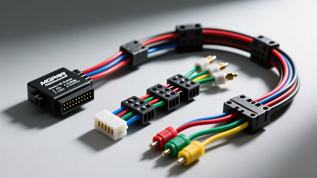
Introduction to the Mopar Magnum Rack Wiring Harness
When performing an engine swap or restoring a classic truck with a Mopar 5.2L (318) or 5.9L (360) Magnum V8, understanding the Magnum rack wiring harness is critical to a successful build. In Mopar terminology, the 'rack' harness typically refers to the engine-mounted sub-harness that routes across the fuel rail (injector rack), connects the ignition coils, and interfaces with the main chassis bulkhead. Unlike modern CAN-bus systems, the 1992-1998 Magnum V8 utilizes a straightforward, speed-density, multi-port fuel injection (MPFI) architecture that is highly adaptable for custom hot rods, Jeeps, and off-road buggies.
This complete diagram walkthrough dissects the OEM Magnum rack wiring harness, detailing the Auto Shutdown (ASD) relay circuits, sequential injector routing, sensor 5V references, and specific Delphi connector pinouts. Whether you are modifying a junkyard pull or integrating an aftermarket standalone ECU, these specifications will ensure your harness is built to SAE J1128 automotive wire standards.
Main Harness Architecture and Bulkhead Integration
The Magnum engine harness connects to the vehicle's main chassis harness via a large, sealed 60-way (early OBD1) or dual 60-way (104-pin OBD2) bulkhead connector located near the firewall. For this walkthrough, we will focus on the highly sought-after 1996-1998 OBD2 5.9L Magnum configuration, which utilizes two 60-way PCM connectors (C1 Black and C2 White). The rack harness branches off from the main loom, wrapping around the intake manifold to service the fuel rail, distributor (or crank/cam sensors on later models), and throttle body.
Table: Critical PCM C1 (Black) Pinout Specifications
The C1 connector handles the majority of the high-current actuator grounds and sensor references. Below is a reference chart for the most vital pins interfacing with the Magnum rack harness.
| Pin | Circuit Name | Wire Color | AWG | Function |
|---|---|---|---|---|
| A1 | ASD Relay Output | Dark Green/Orange (DG/OR) | 14 | Switched 12V feed to injectors and coils |
| A11 | Injector 1 Ground | Dark Blue/Light Green | 18 | PCM switched ground for Cyl 1 |
| A12 | Injector 2 Ground | Dark Blue/Light Blue | 18 | PCM switched ground for Cyl 2 |
| A13 | Injector 3 Ground | Dark Green/Dark Blue | 18 | PCM switched ground for Cyl 3 |
| A14 | Injector 4 Ground | Dark Green/White | 18 | PCM switched ground for Cyl 4 |
| B31 | 5V Reference | Violet/White (VT/WT) | 18 | Shared 5V supply for TPS, MAP, IAT |
| B32 | Sensor Ground | Black/Light Blue (BK/LB) | 18 | Dedicated low-noise ground for sensors |
| C3 | Coil Ground 1 | Dark Gray/Black | 16 | PCM switched ground for coil pack |
| C4 | Coil Ground 2 | Dark Gray/Orange | 16 | PCM switched ground for coil pack |
Note: Mopar wire colors are denoted by Base Color/Tracer Color. DG/OR is universally recognized by Chrysler technicians as the ASD feed wire. If this wire lacks 12V during cranking, the engine will not fire.
The Fuel Rail (Rack) Injector Sub-Harness Walkthrough
The injector rack harness is the most vulnerable section of the Magnum wiring system due to its proximity to the exhaust manifolds and the intense heat radiating from the engine block. The OEM harness uses 18 AWG TXL (Thermoplastic Cross-Linked) wire, which is rated for continuous operation up to 125°C. However, after 20+ years, the loom material becomes brittle, and the injector pigtail connectors suffer from terminal corrosion.
Injector Connector Specifications and Routing
The Magnum V8 uses Delphi Metri-Pack 280 series connectors for the fuel injectors. Each injector receives constant 12V from the ASD Relay via the Dark Green/Orange (DG/OR) wire. This wire is spliced internally within the rack harness to feed all eight injectors. The PCM completes the circuit by pulsing the ground side.
- Feed Wire (Pins A & B on Injector): Dark Green/Orange (18 AWG). Must be protected with high-temp fiberglass sleeving or corrugated loom with heat-reflective tape.
- Ground Wire (Pin C on Injector): Unique color per cylinder (e.g., Cyl 5 is DB/YL, Cyl 6 is DB/TN, Cyl 7 is DG/BK, Cyl 8 is DG/RD).
- Crimp Terminals: When rebuilding the rack harness, use Delphi 12059188 female terminals with silicone wire seals. Standard open-barrel crimps will fail due to fuel vapor intrusion and engine bay moisture.
Sensor Circuit Walkthrough: TPS, MAP, and IAT
The sensors mounted on or near the intake manifold share a common 5-volt reference and sensor ground circuit. A short in the rack harness rubbing against the alternator bracket will pull the 5V reference down to 0V, causing the PCM to trigger a P0122 (TPS Low) and P0107 (MAP Low) simultaneously, instantly putting the engine into limp mode.
- Throttle Position Sensor (TPS): Violet/White (5V Ref), Dark Blue/Light Green (Signal), Black/Light Blue (Ground).
- Manifold Absolute Pressure (MAP): Violet/White (5V Ref), Dark Green/Red (Signal), Black/Light Blue (Ground).
- Intake Air Temperature (IAT): Violet/Brown (Signal), Black/Light Blue (Ground). Note that the IAT uses a thermistor and does not require a 5V reference; the PCM supplies an internal pull-up voltage.
For detailed factory diagnostic procedures and connector cavity views, technicians should consult the Mopar Tech Authority database or equivalent factory service manuals.
Expert Troubleshooting: Magnum Rack Harness Decision Tree
When diagnosing a no-start or rough-running condition on a Magnum swap, follow this symptom-cause-fix decision tree to isolate rack harness failures:
- Symptom: Engine cranks, has spark, but zero fuel injector pulse.
- Cause: ASD Relay not engaging, or DG/OR wire severed between bulkhead and fuel rack.
- Fix: Check PCM Pin A1 for 12V during cranking. Verify ASD relay control ground (Dark Blue/Yellow) at the PCM. Repair DG/OR splice in the rack loom.
- Symptom: Engine runs extremely rich, black smoke, O2 sensors maxed out.
- Cause: Injector ground wires shorted to chassis ground, or PCM driver failure.
- Fix: Disconnect PCM C1. Use a multimeter to check resistance between injector ground pins (A11-A14, etc.) and engine block. It should read OL (Open Loop). If continuity exists, the rack harness is pinched under the intake manifold.
- Symptom: Intermittent stalling when hitting bumps or vibrating at idle.
- Cause: Fretting corrosion in the 60-way bulkhead connector or cracked solder joints in the coil pack pigtail.
- Fix: Extract terminals using a Delphi Metri-Pack removal tool. Clean with electrical contact cleaner and apply dielectric grease (Nyogel 760G) to the bulkhead seal.
Aftermarket Swap Harness vs. OEM Magnum Rack Harness
When adapting a 5.9L Magnum into a non-Mopar chassis (like a classic Bronco or Chevy C10), builders face a choice: modify the OEM rack harness or purchase an aftermarket solution. While companies like MSD and Holley offer universal MPI harnesses, retaining the OEM Magnum rack harness is often preferred for its exact firewall routing and factory loom diameters.
To adapt the OEM harness for a standalone ECU (such as a Holley Terminator X or MegaSquirt), you must re-pin the bulkhead connector. The OEM 14 AWG ASD feeds are retained to power the injectors and coils, but the 18 AWG PCM ground wires are redirected to the standalone ECU's injector output drivers. Ensure your standalone ECU is configured for 'High-Z' (High Impedance) injectors, as the OEM Magnum injectors are saturated-flow, high-impedance units (typically 14.5 ohms). Using a peak-and-hold driver on high-Z injectors will cause premature failure of the ECU's internal MOSFETs.
Final Assembly and Heat Shielding Protocols
The Magnum V8 is notorious for cooking the wiring harness near the passenger side exhaust manifold. When reinstalling the rack harness, you must use corrugated split loom wrapped in adhesive-backed aluminum foil heat tape (rated for 400°F+). Never use standard black vinyl electrical tape in the engine valley or near the exhaust ports; the adhesive will melt, attracting dirt and eventually causing the wires to chafe and short against the aluminum intake manifold. Properly routing the Magnum rack wiring harness away from the steering shaft and exhaust headers ensures reliable, maintenance-free operation for thousands of miles.