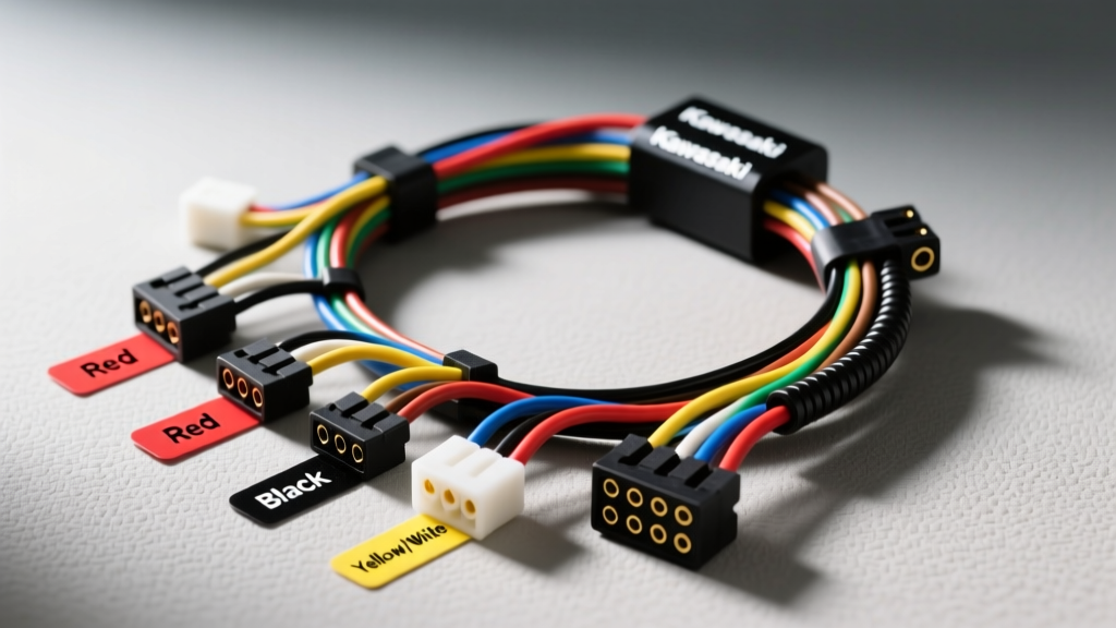
Introduction to the KLF220 Electrical System
The Kawasaki Bayou 220 (KLF220) is legendary for its mechanical simplicity, but its electrical system can become a labyrinth of brittle insulation and corroded connectors after decades of use. Whether you are performing a complete frame-off restoration, troubleshooting a no-spark condition, or installing an aftermarket harness kit, understanding the Kawasaki Bayou 220 wiring harness is critical. This complete diagram walkthrough breaks down the OEM routing, circuit pinouts, wire gauges, and diagnostic procedures required to get your ATV running reliably. Unlike modern fuel-injected machines, the KLF220 relies on a straightforward magneto-stator and CDI system, making it highly serviceable if you understand the foundational wiring architecture.
Main Harness Routing and Junction Points
The main harness on the Bayou 220 originates at the stator under the left-side crankcase cover. The three-phase AC output wires and the pulse coil wires exit through a critical rubber grommet at the upper left of the engine case. Failure Mode Alert: This grommet frequently degrades, allowing oil to wick up into the harness via capillary action, eventually degrading the main junction connectors. From the engine, the harness routes up along the left side of the frame rail, passing beneath the fuel tank, and terminates at the main junction block located just behind the battery box and under the seat. From this central node, sub-harnesses branch forward to the handlebar switches, headlight pod, and ignition coil, while the rear sub-harness routes down the right frame rail to the tail light and brake switches.
Ignition and CDI Circuit Pinout Walkthrough
The heart of the KLF220 ignition system is the Capacitor Discharge Ignition (CDI) unit, typically mounted under the seat near the battery. The CDI connects to the main harness via a sealed 6-pin Sumitomo connector. Understanding this pinout is essential for diagnosing spark issues or adapting an aftermarket ignition module.
- Pin 1 (Black/Yellow): Engine Stop / Kill Switch. When grounded, it shorts the CDI capacitor, killing the spark.
- Pin 2 (Brown): 12V Switched Power. Sourced from the ignition switch via the main fuse.
- Pin 3 (Orange): Ignition Coil Positive. Carries the high-voltage trigger pulse to the primary side of the ignition coil.
- Pin 4 (White/Red): Pulse Coil Positive. Carries the timing signal from the stator's pickup coil.
- Pin 5 (White/Green): Pulse Coil Negative / Signal Ground.
- Pin 6 (Black): Main CDI Ground. Must have absolute continuity to the battery negative terminal.
Stator and Regulator/Rectifier Specifications
The charging system utilizes a 3-phase stator and a combined Regulator/Rectifier (R/R) unit. The stator outputs three Yellow wires (typically 16 AWG OEM, though upgrading to 14 AWG is recommended for heat resistance). These connect to the R/R via a 3-pin sealed connector. The R/R converts the AC voltage to DC and regulates it to approximately 14.2V to 14.8V to charge the battery. The R/R output consists of a Red wire (DC Positive, routed to the battery positive via the main 15A fuse) and a Black wire (Ground, bolted directly to the frame). For optimal performance and to adhere to SAE J1128 standards for low-tension primary cables, ensure all charging system ground connections utilize a star washer to bite through the frame's powdercoat.
Kawasaki Bayou 220 Wire Color and Specification Chart
Reference this chart when tracing circuits or fabricating a custom replacement harness. Wire gauges listed are minimum recommendations based on standard automotive electrical practices and Waytek Wire technical specifications for DC current carrying capacity.
| Circuit Function | OEM Wire Color | Min. AWG | Connector Type |
|---|---|---|---|
| Main Battery Positive | Red | 10 AWG | 8mm Ring Terminal |
| Main Chassis Ground | Black | 10 AWG | 8mm Ring Terminal |
| Stator AC Output (x3) | Yellow | 14 AWG | Sumitomo HM 090 (3-Pin) |
| Pulse Coil Signal | White/Red, White/Green | 20 AWG | Sumitomo HM 090 (2-Pin) |
| CDI to Ignition Coil | Orange | 18 AWG | 6.3mm Spade (Female) |
| Headlight High Beam | White | 18 AWG | 3-Pin Headlight Pigtail |
| Headlight Low Beam | Blue | 18 AWG | 3-Pin Headlight Pigtail |
| Tail / Marker Light | Brown | 18 AWG | Wedge Base / 2.8mm Spade |
| Brake Light Switch | Green/Yellow | 18 AWG | 2.8mm Spade (Female) |
Step-by-Step Diagram Walkthrough: Lighting and Switches
The Bayou 220 lighting circuit is controlled by a multi-position thumb switch on the left handlebar cluster. Power enters the switch via a Brown wire from the main harness. When the switch is moved to 'Park', power is routed to the Brown output wire, illuminating the tail light and front marker lights. Moving the switch to 'Head' sends power to the White (High) or Blue (Low) wires, depending on the position of the dimmer rocker switch. A common failure point in the KLF220 harness is the internal corrosion of this handlebar switch cluster. Because the switch is not fully potted in resin, moisture ingress causes the copper contact plates to oxidize, resulting in a voltage drop that dims the headlight. If you measure more than a 0.5V drop across the switch contacts under load, the switch must be disassembled and cleaned, or the harness modified to use a relay-driven headlight upgrade.
Diagnostic Decision Trees: Troubleshooting the Harness
When the wiring harness is suspected of causing a failure, use these structured diagnostic paths to isolate the fault without throwing unnecessary parts at the machine.
Condition 1: Engine Cranks but Has No Spark
- Test the Kill Circuit: Disconnect the main harness connector at the CDI. Using a multimeter set to continuity, check the Black/Yellow wire in the harness side. With the key ON and the run switch set to RUN, there should be NO continuity to ground. If there is continuity, trace the Black/Yellow wire back to the handlebar kill switch and ignition key switch to find the short.
- Test the Pulse Coil Harness: Measure resistance between the White/Red and White/Green wires at the harness connector (stator side). The specification is 384 to 576 ohms at room temperature. An open circuit (OL) indicates a broken wire inside the stator casing or a severed harness wire near the engine grommet.
- Test the Ignition Coil Feed: Check the Orange wire for continuity from the CDI connector to the primary tab on the ignition coil. Ensure the Black ground wire at the ignition coil has less than 0.2 ohms of resistance to the battery negative terminal.
Condition 2: Battery is Not Charging (Stator/RR Circuit)
- Stator AC Output Test: Disconnect the 3-pin Yellow wire connector between the stator and the R/R. Start the engine and let it idle. Measure AC Voltage between the three Yellow wires (Pin 1 to 2, Pin 2 to 3, Pin 1 to 3). You should see 15-25 VAC at idle. Rev the engine to 3000 RPM; the voltage should rise to 50-70 VAC. If one pair reads zero, the stator or the harness wire is broken.
- R/R DC Output Test: Reconnect the stator. Measure DC Voltage at the battery terminals with the engine running at 3000 RPM. It should read between 13.8V and 14.8V. If the stator AC output is good but DC voltage remains at 12.5V or lower, the Regulator/Rectifier has failed, or the Red/Black harness wires leading to the battery are suffering from severe voltage drop due to corrosion.
Expert Repair and Replacement Best Practices
If your Kawasaki Bayou 220 wiring harness is beyond repair due to rodent damage, UV degradation, or previous owner 'hacks', replacing it with an OEM or high-quality aftermarket kit is the best solution. When installing a new harness, always apply a dielectric grease (such as Nyogel 760G) to all multi-pin connectors before mating them. This prevents galvanic corrosion and blocks moisture intrusion. For any splices that must be made, abandon electrical tape and twist-caps; instead, use adhesive-lined marine-grade heat shrink crimp connectors. Finally, secure the harness to the frame using UV-resistant nylon zip ties and protective split-loom tubing, ensuring at least a 2-inch clearance from the exhaust header and steering stem pivot points to prevent chafing during suspension articulation. For further reference on OEM connector pin retention and extraction, consult the Kawasaki Owner Center Manuals repository to verify specific clip orientations for the Sumitomo housings.