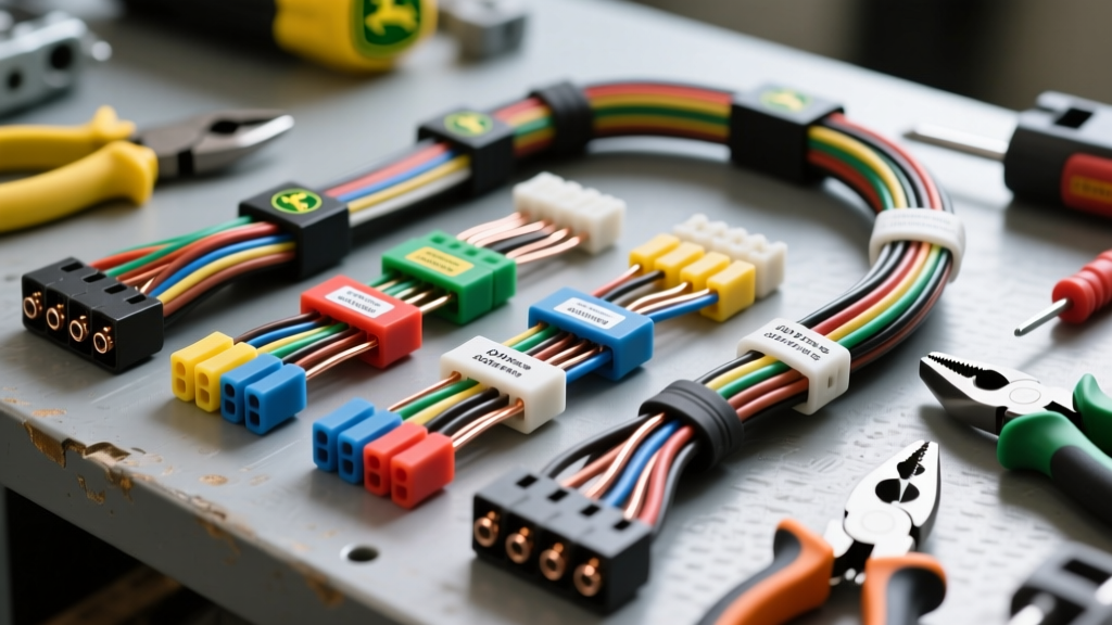
Mastering the John Deere Main Chassis Harness Replacement
Replacing the main chassis wiring harness on a John Deere 100-Series, L-Series, or D-Series lawn tractor is the definitive cure for parasitic battery draws, melted bulkhead connectors, and erratic safety interlock faults. However, blindly swapping wires without consulting the factory john deere wiring harness diagram is a recipe for a fried voltage regulator, a disabled PTO clutch, or a tractor that cranks but refuses to start. Outdoor power equipment operates in high-vibration, high-moisture environments, meaning every connection must be executed to exact OEM specifications.
This comprehensive installation guide bridges the gap between schematic theory and physical execution. We will decode the specific grid-layout diagrams used in John Deere Technical Manuals (TMs), outline the precise crimping tools required for Delphi Weather-Pack and AMP Superseal connectors, and provide a step-by-step routing procedure to ensure your new harness kit survives years of heavy mowing.
Decoding the John Deere Wiring Harness Diagram
Unlike standard automotive schematics, John Deere electrical diagrams utilize a unique alphanumeric grid system to help technicians locate specific circuits quickly. When you pull up the John Deere Technical Publications portal or consult your model-specific TM, you will notice coordinates (e.g., A1, B4) bordering the schematic.
- Grid Coordinates: Used to pinpoint the exact location of a splice, connector, or ground stud on the physical diagram.
- Wire Designations: Wires are often labeled with an "X" or "W" prefix (e.g., X23 for a specific harness branch, W14 for a ground wire).
- Switch Logic: The diagram will explicitly show the Safety Interlock Module (SIM) or Transmission Safety Switch (TSS) logic. Pay close attention to Normally Open (NO) and Normally Closed (NC) designations on the seat switch and brake pedal microswitches. A misread NO/NC symbol is the number one reason a newly installed harness fails the PTO engagement test.
Essential Tools and Harness Kit Components
Do not attempt this installation with generic hardware store crimpers. John Deere harnesses rely on sealed automotive connectors that require specific tooling to maintain their IP67 weather resistance.
- Delphi Packard Crimp Tool: Required for Weather-Pack terminals (common on the ignition switch and stator).
- AMP Superseal Crimp Tool: Necessary for the PTO clutch and seat switch connectors.
- Torque Wrench (Inch-Pound): Critical for the starter solenoid B+ terminal and chassis ground lugs.
- Dielectric Grease & Heat Shrink: Nygel grease for connector cavities; 3M adhesive-lined heat shrink for any inline splices.
- Fiberglass Sleeving: To protect the harness loom where it routes near the exhaust manifold or engine block.
Step-by-Step Main Chassis Harness Installation
Step 1: Battery Isolation and Old Harness Removal
Disconnect the negative (-) battery cable first, followed by the positive (+) cable. Remove the steering wheel and the lower dash tower shroud to expose the main bulkhead connector. Before cutting any zip ties, take high-resolution photos of the harness routing, specifically where the loom passes through the steering column bearing and the frame rail grommets. Unbolt the main chassis ground (usually a 1/4" or 5/16" ring terminal on the lower engine block or frame rail) and the starter solenoid B+ nut. Carefully extract the old harness from the dash tower, noting the factory loom clips.
Step 2: Routing and Securing the New Loom
Begin routing the new harness kit from the rear of the tractor (PTO and seat switch area) forward toward the engine bay. Feed the main trunk through the chassis grommet. Crucial: Ensure the harness does not rest against the steering shaft or the exhaust header. Use the factory-molded loom clips to secure the harness every 6 to 8 inches. Where the harness must cross high-heat zones, slide fiberglass heat-sleeving over the corrugated loom. Secure the loom with UV-resistant nylon cable ties, leaving enough slack near the engine mounts to accommodate engine vibration without putting tension on the connectors.
Step 3: Terminating the Ignition and Safety Interlocks
Connect the dash harness to the main chassis harness via the primary bulkhead connector. Push the halves together until you hear the definitive "click" of the locking tab. Next, wire the ignition switch. The standard John Deere 5-terminal switch uses a Packard 568131-1 connector. Verify the pinout against your diagram: Terminal B (Battery/Red), S (Start/White), A (Accessory/Purple), M (Magneto Kill/Orange), and G (Ground/Black). Apply a small dab of dielectric grease to the terminal cavity before mating the connector to the switch.
Step 4: PTO Clutch and Alternator Connections
The PTO electromagnetic clutch draws significant amperage (typically 3 to 5 amps at 12V). Ensure the Purple 14 AWG feed wire is seated firmly in the AMP Superseal 2-pin connector. For the alternator/stator circuit, connect the two Yellow 14 AWG wires to the stator output. These carry raw AC voltage to the regulator/rectifier. Finally, attach the main Red 10 AWG battery feed to the starter solenoid. According to SAE J1128 standards for low-tension primary cables, the ring terminal must be flush against the solenoid stud. Torque the 5/16" solenoid nut to exactly 9-12 ft-lbs (108-144 in-lbs). Over-torquing will strip the stud; under-torquing will cause arcing and melt the terminal.
John Deere Wire Color and Pinout Reference Chart
Use this quick-reference table to verify your harness kit against the factory schematic before finalizing connections. Wire colors may vary slightly by exact model year, so always defer to your specific TM.
| Circuit Function | Wire Color | AWG Size | Connector Type | Diagnostic Note |
|---|---|---|---|---|
| Starter Solenoid B+ | Red | 10 AWG | 5/16" Ring Terminal | Check for voltage drop under load (max 0.1V). |
| PTO Clutch Feed | Purple | 14 AWG | AMP Superseal 2-Pin | Requires 12V+ at clutch coil for proper engagement. |
| Ignition "S" (Start) | White | 16 AWG | Packard Weather-Pack | Only active in the "Start" key position. |
| Seat Switch Logic | Orange / Gray | 18 AWG | AMP Superseal 4-Pin | Verify NO/NC states with multimeter before mating. |
| Alternator Stator | Yellow (x2) | 14 AWG | Packard 2-Pin | Outputs AC voltage; tests at ~28V AC at high RPM. |
| Main Chassis Ground | Black | 10 AWG | 5/16" Ring Terminal | Torque to 15-20 ft-lbs on clean, bare metal. |
Environmental Sealing and Vibration Proofing
A wiring harness kit is only as good as its environmental seals. John Deere tractors are subjected to pressure washing, fertilizer dust, and constant chassis flex. After all connectors are mated, inject a small amount of Nygel dielectric grease into the rear wire-entry seals of the Weather-Pack and Superseal connectors. This prevents moisture wicking, where water travels down the wire strands and corrodes the terminal from the inside out. For any harness branches that hang freely, use split-loom tubing and secure it with adhesive-backed mounting pads to prevent the harness from vibrating against the mower deck or frame.
Troubleshooting Common Post-Installation Faults
Even with a perfect physical installation, the John Deere Safety Interlock Module can throw a wrench in the startup sequence. Use this decision tree if your tractor fails to operate correctly after the harness swap:
- Symptom: Engine cranks, but dies immediately when the brake pedal is released.
Cause: The brake pedal TSS (Transmission Safety Switch) or the seat switch is miswired or failing to close the circuit. The SIM interprets the open circuit as the operator leaving the seat while the PTO is engaged, triggering the kill wire (Terminal M). Check the Orange/Gray 18 AWG wires at the AMP 4-pin connector for continuity. - Symptom: PTO switch clicks, but the clutch does not engage.
Cause: Voltage drop in the Purple 14 AWG PTO feed wire. Use a multimeter to test voltage at the clutch coil while the PTO switch is pulled. If it reads below 11.5V, check the bulkhead connector pins for improper seating or a weak ground at the clutch mounting bracket. - Symptom: Battery drains overnight.
Cause: The voltage regulator/rectifier is back-feeding. Ensure the Yellow stator wires and the Red B+ sense wire on the regulator are connected to the correct terminals as dictated by the schematic. A reversed sense wire will keep the regulator active, draining the battery in 12-24 hours.
Final Verification and Testing
Before reinstalling the dash shrouds and steering wheel, reconnect the battery (Positive first, then Negative). Turn the key to the "Run" position (do not crank). Verify that the dashboard warning lights illuminate and the fuel solenoid clicks. Engage the PTO switch with the operator in the seat; you should hear a loud, distinct "clack" from the electromagnetic clutch. Finally, start the engine and use a multimeter to verify the alternator is outputting between 13.8V and 14.4V DC at the battery terminals at half-throttle. For further reference on proper automotive wire gauge selection and temperature ratings, consult the TE Connectivity Superseal automotive connector guidelines to ensure your harness kit maintains OEM-level integrity for years to come.