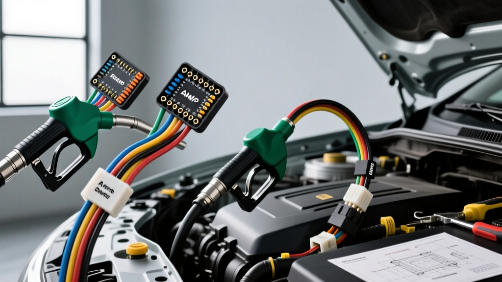
The Critical Role of the Fuel Pump Wiring Harness
Modern electronic fuel injection (EFI) systems demand consistent, high-volume fuel delivery, placing immense electrical loads on the fuel pump wiring harness. Whether you are restoring a classic muscle car with an EFI swap, upgrading a late-model truck for towing, or replacing a degraded factory harness, selecting the correct fuel pump wiring harness is non-negotiable. A marginal voltage drop across undersized wires or corroded terminals can reduce pump output by 10 to 15 percent, leading to lean conditions, vapor lock, or catastrophic engine failure under load.
According to the SAE J1128 Standard for Low Tension Primary Cable, automotive wiring must withstand extreme undercarriage temperatures, chemical exposure from road salts, and constant vibration. This guide compares OEM replacement assemblies against universal aftermarket pigtail kits, providing the technical specifications necessary to make an informed selection for your specific application.
OEM Replacement vs. Universal Aftermarket Harness Kits
OEM Harness Assemblies: The Factory Standard
Original Equipment Manufacturer (OEM) fuel pump wiring harnesses are typically sold as part of the complete fuel pump module assembly or as a dedicated drop-in pigtail. These harnesses feature injection-molded connector housings, factory-crimped open-barrel terminals, and specific wire loom routing designed for the exact geometry of your fuel tank.
- Pros: Guaranteed fitment, correct locking tab geometry, sealed weather-pack barriers, and exact wire color coding matching the factory service manual.
- Cons: High cost, limited availability for discontinued models, and factory wire gauges are often sized only for the stock pump amperage, not high-flow aftermarket upgrades.
Aftermarket and Universal Pigtail Kits
Universal fuel pump wiring harness kits, often utilizing Delphi Metri-Pack or Molex MX150 connectors, are the preferred choice for performance upgrades. When swapping a stock 15-amp pump for a 340 liters-per-hour (lph) brushless pump drawing 25 amps, the factory 16-gauge wires will overheat. Aftermarket kits allow you to select heavier gauge wiring and high-current terminals.
- Pros: Customizable wire lengths, availability of 12 AWG and 10 AWG high-current wires, cost-effective, and ideal for custom fuel cell installations.
- Cons: Requires proper crimping tools, heat-shrink sealing, and manual routing. Poorly executed crimps on universal kits are a leading cause of fuel system fires.
Wire Gauge (AWG) and Amperage Specification Matrix
Selecting the correct American Wire Gauge (AWG) is the most critical step in harness selection. Undersized wiring creates resistance, generating heat and dropping voltage before it reaches the pump. The following matrix outlines the requirements based on Haynes Automotive Wiring Basics and standard chassis wiring ampacity charts.
| Wire Gauge (AWG) | Max Amperage (Chassis) | Voltage Drop @ 10ft (Round Trip) | Typical Fuel Pump Application |
|---|---|---|---|
| 16 AWG | 10 Amps | 0.81V | Low-pressure lift pumps, carburetor solenoids |
| 14 AWG | 15 Amps | 0.51V | Stock Bosch 044, GM TPI, standard 190 lph pumps |
| 12 AWG | 20 Amps | 0.32V | Walbro 255 lph, AEM 320 lph, Ford Modular V8 |
| 10 AWG | 30 Amps | 0.20V | Walbro 450 lph, AEM 340, Twin-pump setups |
| 8 AWG | 40 Amps | 0.13V | Brushless pump controllers, drag racing twin 450s |
Note: Always calculate voltage drop using the total circuit length (positive wire length + ground wire length). A 10-foot run from the relay to the tank actually represents 20 feet of total conductor length.
Connector Architecture and Pinout Configurations
The physical interface between the chassis harness and the in-tank pump is a primary failure point. The industry standard for high-current fuel pump connections is the Delphi Metri-Pack 280 Series, capable of handling up to 30 amps per cavity when properly crimped and sealed.
Common GM LS / Late-Model 4-Pin Pinout
Many GM vehicles from 1999 to present utilize a 4-pin Delphi connector at the fuel tank sending unit. When wiring an aftermarket harness to this configuration, adhere to the following pinout:
- Pin A (Purple): Fuel Level Sender Signal (Low current, 18-20 AWG)
- Pin B (Black): Chassis Ground for Sender (18-20 AWG)
- Pin C (Red or Pink): 12V Fuel Pump Power (High current, 12-10 AWG)
- Pin D (Light Green/White): Fuel Level Sender Ground / Return (18-20 AWG)
Ford Modular 6-Pin / 7-Pin USCAR Configurations
Ford vehicles often use USCAR-standard connectors. The high-current pump power is typically routed through a heavy Black/Yellow wire, while the ground is Black/White. When upgrading Ford harnesses, ensure the terminal tension in the female USCAR housing is checked with a pin gauge; loose tension causes arcing and melted plastic housings.
Real-World Failure Modes and Diagnostic Insights
Before installing a new fuel pump wiring harness, it is vital to understand why the previous harness failed. Replacing a harness without addressing the root cause will result in repeated failures.
1. Melted Connector Pigtails
Symptom: Intermittent stalling, smell of burning plastic near the rear axle, melted plastic around Pin C (Power).
Cause: Terminal fretting corrosion or loss of spring tension in the female terminal. As resistance increases at the connection point, heat builds up. Since the fuel pump draws continuous current, the heat melts the nylon housing.
Fix: Never splice a new wire into a melted terminal. Cut the harness back to clean, unoxidized copper, and install a new pigtail kit using adhesive-lined marine-grade heat shrink.
2. Ground Loop and Sender Inaccuracy
Symptom: Fuel pump operates normally, but the dashboard fuel gauge reads erratic or completely empty.
Cause: The fuel pump power ground and the fuel level sender ground are often tied together at the tank flange. If the tank strap ground to the chassis is corroded, the high-current pump ground seeks a path through the low-current sender signal wire, frying the gauge cluster resistor.
Fix: Run a dedicated 12 AWG ground wire directly from the fuel pump module flange to a clean, bare-metal point on the chassis, bypassing the tank straps entirely.
Step-by-Step Selection and Installation Protocol
To ensure a reliable, high-flow fuel delivery system, follow this installation protocol when deploying your selected harness kit:
- Verify Relay and Fuse Sizing: If upgrading to a 10 AWG harness for a 450 lph pump, ensure your under-hood relay is rated for at least 40 amps and the inline fuse is sized to 30 amps (slow-blow).
- Use the Correct Crimp Tool: Delphi Metri-Pack terminals utilize an open-barrel (M-shape) crimp. Do not use standard closed-barrel crimpers. Use a dedicated open-barrel tool to ensure the wire crimp and insulation crimp are formed correctly without piercing the conductor.
- Apply Dielectric Grease: Before mating the new harness connector to the pump flange, apply a small amount of silicone dielectric grease to the terminals to prevent moisture ingress and galvanic corrosion.
- Secure the Loom: Use Tesa tape or split-loom tubing to protect the harness from chafing against the fuel tank straps or exhaust heat shields. Secure the harness with P-clips every 12 inches to prevent vibration fatigue at the crimp joints.
- Perform a Voltage Drop Test: After installation, back-probe the connector at the tank with the pump running under load. Measure the voltage between the battery positive and the pump power pin. A reading lower than 13.0 volts indicates excessive resistance in the new harness or supply circuit.