Decoding Automotive Electrical Wiring Harnesses: The LS3 E38 ECU Walkthrough
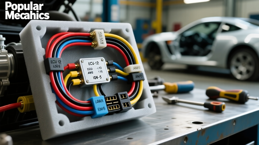
When building or troubleshooting modern engine swap kits, understanding how to read a schematic is just as critical as crimping a weather-pack connector. The transition from simple point-to-point circuits to highly integrated electrical wiring harnesses automotive systems means that a single misrouted 5-volt reference can cascade into multiple ECU failure codes. In this complete diagram walkthrough, we will dissect the General Motors LS3 58x (E38 ECU) engine harness—a benchmark in the aftermarket harness-kits industry—to demonstrate how to trace power distribution, sensor networks, and CAN bus topologies.
1. The Diagram Legend and SAE Wire Standards
Before tracing a single circuit, you must interpret the diagram's legend. Authoritative wiring diagrams adhere to SAE J1128 standards for low-tension primary cable. This standard dictates not only the copper stranding but the insulation material. For engine bay harness kits, you will see XLPE (Cross-Linked Polyethylene) rated for 125°C, rather than standard PVC rated for 90°C.
Wire colors in GM schematics use a two-letter abbreviation. For example, DK GRN is Dark Green, and TN/WH is Tan with a White tracer. The tracer indicates a secondary stripe, crucial for differentiating between multiple circuits sharing the same primary color family.
Table 1: LS3 Harness AWG Specifications & Applications
| AWG Size | Metric (mm²) | Insulation Type | Harness Application |
|---|---|---|---|
| 18 AWG | 0.80 | XLPE | 5V Sensor References, Low-current signals (MAP, TPS) |
| 16 AWG | 1.30 | XLPE | Ignition coil triggers, Injector PWM grounds |
| 14 AWG | 2.00 | XLPE | Switched 12V feeds, O2 sensor heater circuits |
| 10 AWG | 5.00 | XLPE | Main ECU power feeds, High-amperage grounds |
| 8 AWG | 8.00 | XLPE | Alternator main output, Starter motor solenoid feeds |
2. Power Distribution and Fuse Block Routing
A proper diagram walkthrough begins at the battery and moves toward the ECU. In the LS3 harness kit, the main power distribution originates at the underhood fuse block. You will trace the B+ (Battery Positive) circuits, typically colored OG (Orange) or RD (Red) in 10 AWG or 12 AWG.
Look for the Ignition 1 (IGN1) and Crank circuits on the diagram. These are usually PK (Pink) or YE (Yellow) in 14 AWG. A common failure mode in aftermarket swaps is routing the ECU's main relay trigger through a low-amperage toggle switch. The diagram will show this circuit passing through a 30A Bosch-style relay. The relay coil draws roughly 150mA, but the switched contacts must handle the 20A+ inrush current of the ECU and fuel pump prime.
3. ECU Connector Pinout Walkthrough (E38 X1 & X2)
The core of any engine harness kit is the ECU connection. The GM E38 uses three main connectors: X1 (Black), X2 (Gray), and X3 (Blue). Let's walk through the X1 connector, which houses the primary engine management sensors.
When reading the pinout chart on the diagram, note the cavity number, circuit number, wire color, and function. For the Manifold Absolute Pressure (MAP) sensor, the diagram highlights a 3-wire circuit:
- Pin 1 (Circuit 598):
GY(Gray) - 5-Volt Reference. This originates from the ECU's internal voltage regulator. If the diagram shows this line splicing to the Throttle Position Sensor (TPS), an open circuit here will kill both sensors. - Pin 2 (Circuit 416):
LT GRN(Light Green) - MAP Signal. This is a 0-5V analog return. - Pin 3 (Circuit 476):
BK/WH(Black/White) - Low Reference (Sensor Ground). This is NOT a chassis ground. It returns directly to the ECU's internal analog-to-digital converter ground plane.
Table 2: Critical E38 X1 Connector Pinout Reference
| Pin Cavity | Wire Color | Circuit Function | Diagnostic Voltage (KOEO) |
|---|---|---|---|
| 1 | Gray (GY) | 5V Reference 1 (MAP/TPS) | 4.9V - 5.1V |
| 2 | Light Green (LT GRN) | MAP Sensor Signal | ~1.0V (Atmospheric) |
| 3 | Black/White (BK/WH) | Low Reference (Sensor Ground) | < 0.05V |
| 12 | Tan (TN) | Camshaft Position Sensor Signal | 0V / 12V Square Wave |
| 13 | Dark Blue (DK BLU) | Crankshaft Position Sensor Signal | 0V / 12V Square Wave |
4. CAN Bus Topology and Twisted Pair Routing
Modern electrical wiring harnesses automotive systems rely heavily on Controller Area Network (CAN) bus communication. On the diagram, you will identify the CAN High (CAN-H) and CAN Low (CAN-L) circuits, typically DK GRN (Dark Green) and DK BLU (Dark Blue) respectively.
The schematic will explicitly show these wires as a twisted pair. According to GM Upfitter guidelines and SAE standards, this twist must be maintained at 3 to 5 twists per inch to reject electromagnetic interference (EMI) from the ignition coils and alternator. The diagram will also indicate the location of the 120-ohm terminating resistors. In a standalone harness kit, one 120-ohm resistor is internal to the ECU, and the second must be placed across the CAN-H and CAN-L wires at the opposite end of the bus (often inside the OBD-II diagnostic port connector).
When diagnosing CAN bus issues, a standard multimeter will show CAN-H resting at roughly 2.5V and CAN-L at 2.5V. Under load, CAN-H spikes to 3.5V and CAN-L drops to 1.5V. If the diagram shows a splice or a connector in the CAN line, this is your primary suspect for impedance mismatches causing bus-off errors.
5. Grounding Strategy and Splice Packs
A wiring diagram is incomplete without tracing the ground nodes, designated with an 'E' (Earth) or 'G' prefix. The LS3 harness relies on dedicated ground rings rather than relying on the engine block-to-chassis strap alone.
Locate G100 and G200 on the schematic. These are the primary ECU power grounds. The diagram will show multiple 10 AWG and 14 AWG black wires converging into a single ring terminal. When installing the harness kit, these ring terminals must be secured to clean, bare metal on the cylinder head or engine block. The hardware must be torqued to 10 Nm (89 lb-in) to ensure a gas-tight connection that prevents micro-arcing and subsequent ECU driver failure.
Never use dielectric grease on the mating surface of the ground ring terminal and the engine block; grease is an insulator and will increase resistance. Apply it only to the exposed threads and the exterior of the nut to prevent galvanic corrosion between the copper ring and the aluminum block.
Additionally, look for Splice Packs (SP) on the diagram. These are inline, sealed junction nodes where multiple wires of the same circuit are joined. For example, SP105 might distribute the 5V reference to four different sensors. If you are troubleshooting a 5V Reference Circuit Low code, the diagram tells you to isolate the splice pack and test each branch individually to find the shorted sensor.
6. Troubleshooting the Harness Using the Schematic
When a harness kit fails a continuity test, the diagram is your decision tree. Here is a professional workflow for tracing an open circuit in the fuel injector driver (e.g., Cylinder 1 Injector Control, Pin 45 on X2, LT BLU wire):
- Verify the Source: Check for 12V at the injector harness connector (switched side) with the ignition ON.
- Trace the Schematic: Follow the
LT BLUwire from the injector plug back to the ECU X2 connector, Pin 45. - Check Intermediate Connectors: The diagram will show any inline bulkhead connectors (e.g., C100 firewall pass-through). Probe the female terminal on the harness side for continuity to the ECU pin.
- Load Test: Use a headlight bulb or a dedicated load-probe rather than a standard high-impedance multimeter. A multimeter might show continuity through a single strand of copper, but a load test will reveal if the wire can actually carry the 4-amp peak current required to fire the injector.
For pulse-width modulated (PWM) circuits like the electronic throttle body (ETB), the diagram will show dual H-bridge driver circuits. You must verify that the ECU is not cross-firing the coils by checking the isolation between the control and return wires at the harness connector.
Conclusion
Mastering the interpretation of electrical wiring harnesses automotive diagrams transforms a daunting bundle of taped wires into a logical, traceable network. By understanding SAE color codes, AWG current capacities, and ECU pinout topologies, you can confidently install, modify, and diagnose complex engine swap harness kits. Always cross-reference your physical harness against the manufacturer's latest schematic revision to account for mid-year production changes and updated splice pack locations.